Chemical heat exchange device

A heat exchange equipment and chemical technology, applied in lighting and heating equipment, heat exchanger types, indirect heat exchangers, etc., can solve problems such as the risk of large pipe blockage, avoid internal pipe blockage, reasonable structure, and heat exchange effect. Good results

Active Publication Date: 2019-04-12
江苏锐深化工机械科技有限公司
View PDF8 Cites 8 Cited by
  • Summary
  • Abstract
  • Description
  • Claims
  • Application Information

AI Technical Summary

Problems solved by technology

For some liquids that are not easy to agglomerate and have few impurities, the heat exchanger can adapt well; for some liquids that are easy to agglomerate and have a lot of impurities, there will be a greater risk of pipe blockage in the fluid pipe

Method used


Image

  • Chemical heat exchange device
  • Chemical heat exchange device
  • Chemical heat exchange device

Examples


Embodiment 1

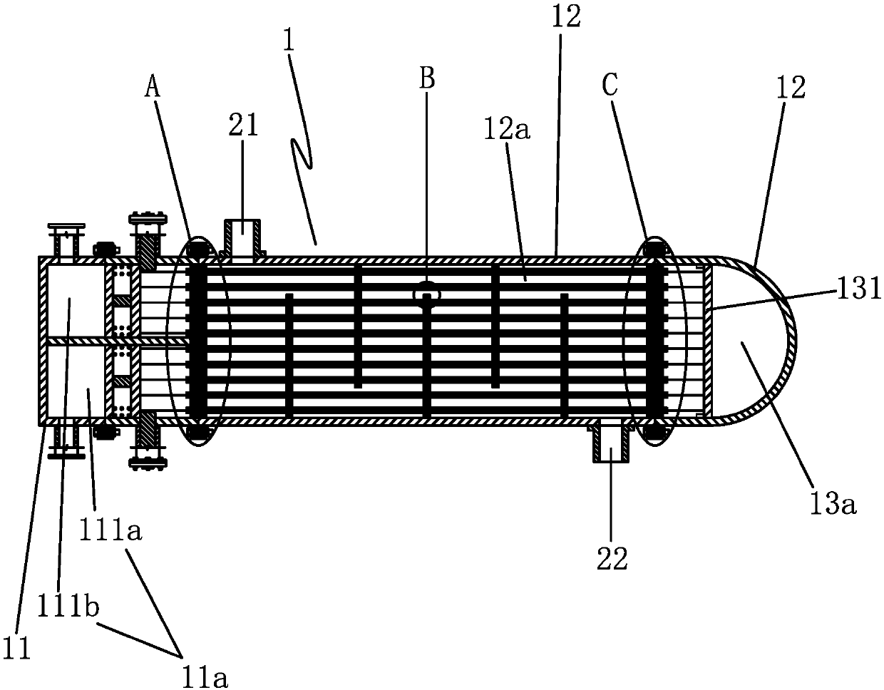
[0037] Embodiment 1: as Figure 1 to Figure 5 as shown,

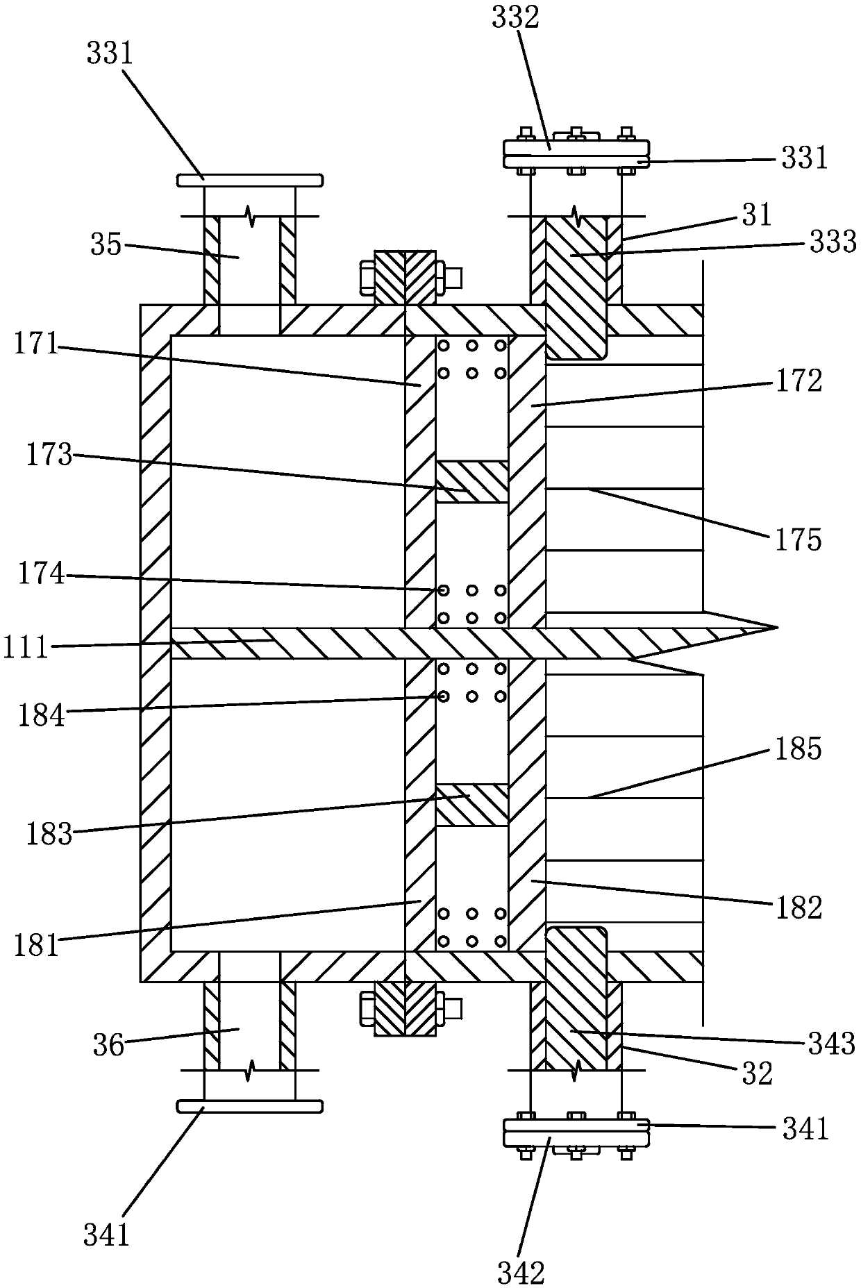
[0038] A chemical heat exchange device, comprising a main shell 1, an inner chamber liquid inlet pipe 21, an inner chamber liquid outlet pipe 22, an outer chamber liquid inlet pipe 31 and an outer chamber liquid outlet pipe 32;

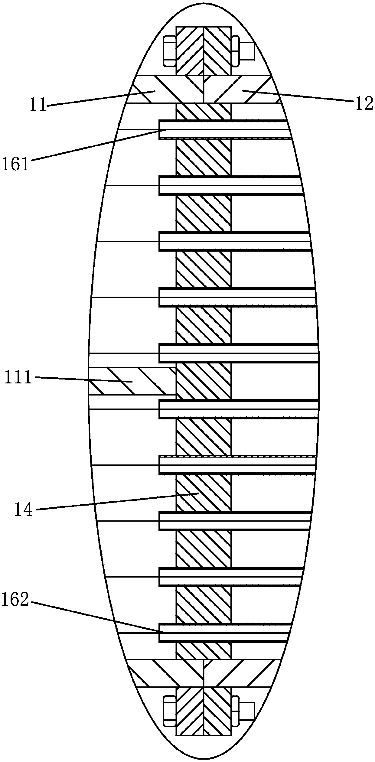
[0039] The main casing includes a front shell head 11, a shell tube 12 and a rear shell head 13. One end of the shell tube is connected to the front shell head by a number of connecting bolts, the joint between the shell tube and the front shell head is sealed, and the other end of the shell tube is connected to the rear The shell head is connected by several connecting bolts, and the connection between the shell tube and the rear shell head is sealed;

[0040] The front of the main housing is provided with a front seat plate 14, a rear seat plate 15, a plurality of inner liquid inlet pipes 161 and a plurality of inner liquid outlet pipes 162, the front seat plate and the front shell head join...

Embodiment 2

[0050] Embodiment 2: based on embodiment 1, as Figure 6 to Figure 11 as shown,

[0051] It also includes an outer frame and an outer shaft 4 coaxially arranged with the shell tube. The outer frame is provided with an outer seat 51, and the outer seat is provided with a guide sleeve 52. One end of the outer shaft is connected with the rear shell head, and the outer shaft is connected with the The guide sleeve is slidingly connected, the slidable direction of the outer shaft is parallel to the axis of the shell tube, the guide sleeve is connected to the outer seat in rotation, the center line of rotation of the guide sleeve coincides with the axis of the shell tube, and an inner ring seat 132 is provided on the outer wall of the rear shell head; The outer frame is provided with a cleaning turbine pump 53, a guide fixing seat 54 and a cleaning drive mechanism. The cleaning drive mechanism includes a first connecting rod 61, a second connecting rod 62, a driving lever 63, a clean...

Embodiment 3

[0054] Embodiment 3: based on embodiment 1, as Figure 12 to Figure 16 as shown,

[0055] It also includes an outer frame and an outer shaft 4 coaxially arranged with the shell tube. The outer frame is provided with an outer seat 51, and the outer seat is provided with a guide sleeve 52. One end of the outer shaft is connected with the rear shell head, and the outer shaft is connected with the The guide sleeve is slidingly connected, the slidable direction of the outer shaft is parallel to the axis of the shell tube, the guide sleeve is connected to the outer seat in rotation, the center line of rotation of the guide sleeve coincides with the axis of the shell tube, and an inner ring seat 132 is provided on the outer wall of the rear shell head; The outer frame is provided with a cleaning piston pump, a guide first seat 71, a guide second seat 72 and a cleaning drive mechanism, and the cleaning drive mechanism includes a first transmission rod 81, a second transmission rod 82,...


PUM


Abstract

The invention discloses a chemical heat exchange device. The chemical heat exchange device comprises a main shell body, an inner cavity liquid inlet pipe, an inner cavity liquid outlet pipe, an outercavity liquid inlet pipe and an outer cavity liquid outlet pipe, wherein the main shell body comprises a front shell head, a shell pipe and a rear shell head, and a front seat plate, a rear seat plate, a plurality of inner liquid inlet pipes and a plurality of inner liquid outlet pipes are arranged in front of the main shell body. An inlet self-dredging structure and an outlet self-dredging structure are arranged in front of the main shell body, wherein the inlet self-dredging structure comprises an inlet fixed plate, an inlet movable plate, a plurality of inlet springs and a plurality of inlet dredging inhaul cables, and the outlet self-dredging structure comprises an outlet fixed plate, an outlet moving plate, an outlet limiting block, a plurality of springs and a plurality of dredging inhaul cables. The chemical heat exchange device has the beneficial effects that the structure is reasonable, different liquid passages can be provided for the two liquids that need heat exchange, andtherefore heat exchange between the two liquids can be realized; and in the heat exchange process, the contact area is large, and the heat exchange effect is good. The chemical heat exchange device also has an automatic dredging structure to avoid the internal blockage problem.

Description

technical field [0001] The invention belongs to the technical field of heat exchange, and in particular relates to chemical heat exchange equipment. Background technique [0002] A heat exchanger is a device that transfers part of the heat of a hot fluid to a cold fluid, also known as a heat exchanger. Heat exchangers play an important role in chemical, petroleum, power, food and many other industrial productions. In chemical production, heat exchangers can also be used as heaters, coolers, condensers, evaporators and reboilers. , is widely used. Since the heat exchanger needs to exchange heat for two liquids, two different liquid passages are required, one of which is the channel inside the heat exchanger shell itself, and the other is a plurality of passages arranged in the heat exchanger shell. For the fluid pipe, the channel diameter inside the heat exchanger shell itself is very large, while the diameter of the fluid pipe is relatively small. As we all know, there ar...

Claims


Application Information

Patent Timeline
Patent Type & Authority Applications(China)
IPC IPC(8): F28D7/16F28G3/12F28G15/04
CPCF28D7/1623F28G3/12F28G15/04
Inventor 王楠
Owner 江苏锐深化工机械科技有限公司
Why Eureka
Try Eureka