Novel heat exchange stirring shaft and tubular reactor

A technology for tubular reactors and stirring shafts, which is applied in chemical/physical/physicochemical fixed reactors, mixer accessories, mixers with rotating stirring devices, etc. Problems such as high energy consumption of the device structure, increased heat transfer load, etc., achieve the effect of saving internal space, occupying a small space, and improving heat transfer efficiency

Active Publication Date: 2016-12-07
HIMILE MECHANICAL MFG
View PDF7 Cites 7 Cited by
  • Summary
  • Abstract
  • Description
  • Claims
  • Application Information

AI Technical Summary

Problems solved by technology

[0002] Chemical reactions usually generate a lot of heat, so the reactor is often equipped with a heat exchange device. The heat exchange device with a mechanical stirrer structure can improve the heat exchange and stirring capacity of the reactor. For example, adding a scraper to the ribbon stirrer In order to improve the heat transfer coefficient of the jacket, however, this method makes the structure of the reactor and the stirrer complex, and at a certain stirring speed, the stirring power increased by the scraper will be converted into stirring heat, which increases the heat transfer load
[0003] The heat exchange device structure of the existing mechanical stirrer has high energy consumption and poor heat exchange effect, and the existing mechanical stirrer can only play the role of stirring and heat exchange. When the chemical reaction is carried out in the tubular reactor, The reactant raw material needs to enter from one end of the tubular reactor, and after the chemical reaction in the tube, it is output from the other end of the tubular reactor, which requires that the mechanical stirrer in the tubular reactor not only needs stirring and heat exchange It also needs to have the function of transporting the reactant raw material from one end of the tubular reactor to the other end

Method used


Image

  • Novel heat exchange stirring shaft and tubular reactor
  • Novel heat exchange stirring shaft and tubular reactor

Examples


Embodiment Construction

[0025] In order to facilitate the understanding of those skilled in the art, the present invention will be further described below in conjunction with the accompanying drawings.

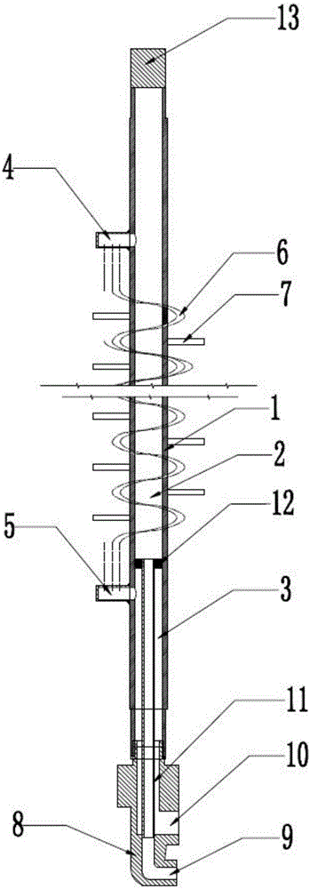
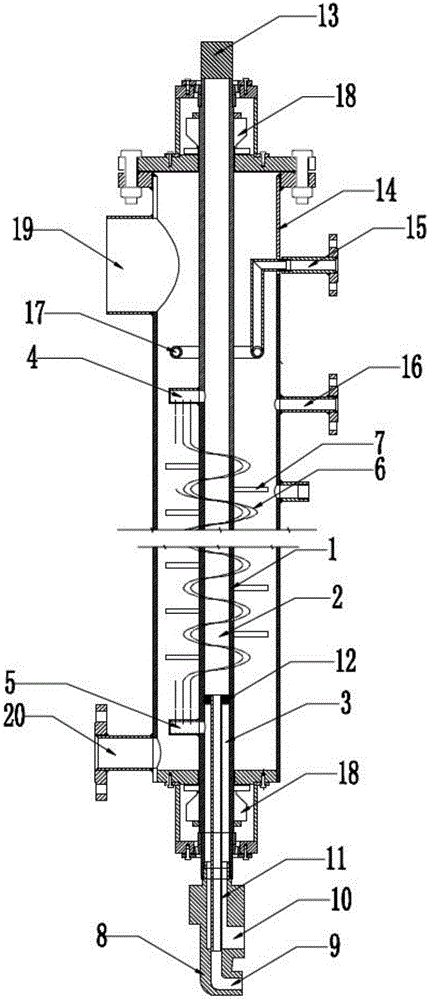
[0026] figure 1 It is a schematic diagram of the overall structure of a new type of heat exchangeable stirring shaft in the present invention, including a main shaft 1, inside the main shaft 1 there are a first chamber 2 and a second chamber 3 isolated from each other, and the first chamber 2 and the second chamber 3 are all provided with an opening on one end of the main shaft 1, the main shaft 1 is provided with a first connecting pipe 4 communicating with the first chamber 2, and the main shaft 1 is provided with a second connecting pipe 5 communicating with the second chamber 3, the first A winding pipe 6 is provided between the connecting pipe 4 and the second connecting pipe 5 for communication, and a plurality of stirring columns 7 are provided on the main shaft 1 .

[0027] One end of the ma...


PUM


Abstract

The invention discloses a novel heat exchange stirring shaft, and belongs to the field of chemical reaction devices. The novel heat exchange stirring shaft comprises a main shaft, wherein a first chamber and a second chamber which are isolated from each other are formed in the main shaft; an opening is formed in each of the first and second chambers at one end of the main shaft; a first connecting pipe communicated with the first chamber is arranged on the main shaft; a second connecting pipe communicated with the second chamber is arranged on the main shaft; at least one spiral pipe for communication is arranged between the first and second connecting pipes. According to the novel heat exchange stirring shaft, a heat exchange medium is introduced into an inner communicated pipeline area to implement heat exchange in a reactor; by a structure formed by spirally winding the main shaft with the spiral pipe, a function of stirring a reaction raw material is realized, and meanwhile, the reaction raw material is driven to be delivered to one end of the axial direction of the main shaft; a heat exchange pipeline can be in contact with the reaction raw material more fully by the rotary movement of stirring columns, so that the heat exchange efficiency is greatly improved.

Description

technical field [0001] The invention relates to the field of chemical reaction devices, in particular to a novel heat-exchangeable stirring shaft and a tubular reactor. Background technique [0002] Chemical reactions usually generate a lot of heat, so the reactor is often equipped with a heat exchange device. The heat exchange device with a mechanical stirrer structure can improve the heat exchange and stirring capacity of the reactor. For example, adding a scraper to the ribbon stirrer In order to improve the heat transfer coefficient of the jacket, however, this method makes the structure of the reactor and the stirrer complex, and at a certain stirring speed, the stirring power increased by the scraper will be converted into stirring heat, which increases the heat transfer load. [0003] The heat exchange device structure of the existing mechanical stirrer has high energy consumption and poor heat exchange effect, and the existing mechanical stirrer can only play the rol...

Claims


Application Information

Patent Timeline
Patent Type & Authority Applications(China)
IPC IPC(8): B01F7/16B01F15/06B01F15/02B01J19/18
CPCB01J19/1812B01F27/1921B01F27/80B01F35/71705B01F35/71B01F35/93B01F2035/99
Inventor 刘庆荣杨智华丁全有魏晓杨茜
Owner HIMILE MECHANICAL MFG
Why Eureka
Try Eureka