
Packaging material provided with cushioning members

a technology of cushioning and packaging material, which is applied in the field of packaging materials, can solve the problems of box collapse, box durability decline, and easy damage to electrical equipment, and achieve the effects of improving the reliability of transportation of products, and ensuring the safety of products

Inactive Publication Date: 2005-07-28
ORION ELECTRIC CO LTD
View PDF2 Cites 16 Cited by
  • Summary
  • Abstract
  • Description
  • Claims
  • Application Information

AI Technical Summary

Benefits of technology

[0008] Therefore, an object of the present invention is to provide a packaging material capable of preventing positional shift of cushioning members when electrical equipment and the like is inserted in the packaging box without causing a lowering of the strength and durability of a packaging box; and, moreover, improving a cushioning effect for a packaged object such as electrical equipment without causing a cost increase.

Problems solved by technology

Especially, electrical equipment has a structure in which electronic parts and precise mechanical parts are combined together, so that the electrical equipment is easily affected by an impact.
However, since the cut and raised parts are formed in the internal surface of the packaging box, the durability of the box lowers greatly, and there is the possibility that the box collapses during the transportation of the product.
Although the material of the packaging box can be changed to a stronger one, the price of the packaging box increases, and the cost of the packaging material increases.
Although the packaging box and cushioning members can be enlarged, the material cost increases, and, in addition, the transportation expenses increases since the packaging box being transported becomes bulky, to give rise to problems.
However, since the same engaging parts are provided on the front and rear sides of the cushioning members, there is the possibility that, when a product whose shapes of the left and right cushioning members are different, such as a television set is packaged, the cushioning members to be arranged on the left and right sides of the product be fixed to wrong sides thereof.
Furthermore, since cut and raised parts are formed on the panel walls of the packaging box, through holes are formed thereon and the product and cushioning members contained in the box are seen from the outside therethrough, and accordingly, the external appearance of the product in a packaged condition is spoiled.

Method used


Image

  • Packaging material provided with cushioning members
  • Packaging material provided with cushioning members
  • Packaging material provided with cushioning members

Examples


first embodiment

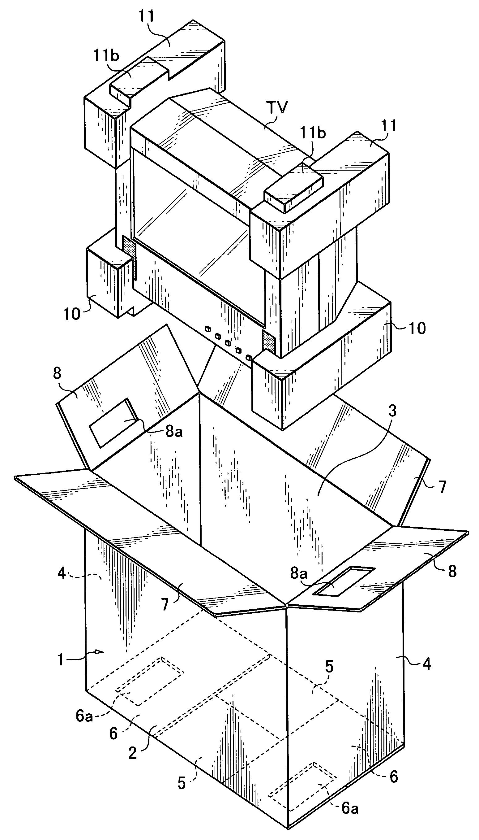
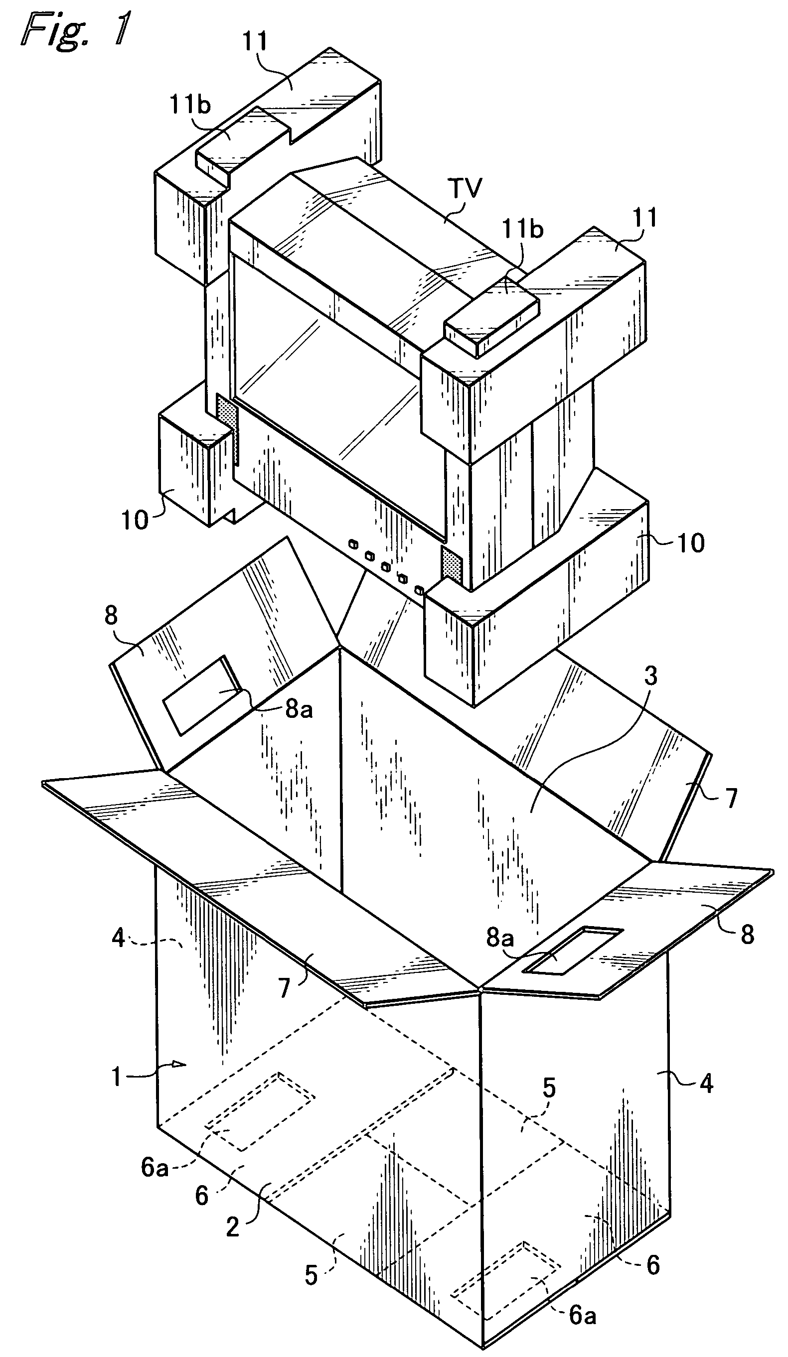
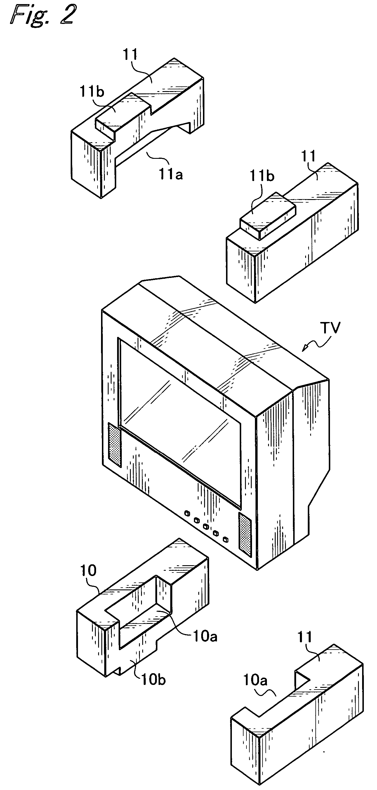
[0030] FIGS. 1 to 8 show the packaging material according to the present invention, which includes a packaging box 1 made of a corrugated board, and cushioning members 10, 10 and 11, 11 made of expanded polystyrene, and which is formed so as to package a television set TV. The packaging box 1 is formed rectangular of a front panel 2 constituting a front wall, a rear panel 3, left and right side panels 4, 4, bottom side front and rear outer flaps 5, 5 constituting a bottom panel, bottom side left and right inner flaps 6, 6, cover side front and rear outer flaps 7, 7 and cover side left and right inner flaps 8, 8. The bottom side left and right inner flaps 6, 6 and cover side left and right inner flaps 8, 8 are provided with through holes 6a, 6a, 8a, 8a in which parts of the cushioning members are fitted. After the bottom side left and right inner flaps 6, 6 are folded, the bottom side front and rear outer flaps 5, 5 are folded to form the bottom panel. Therefore, the through holes 6a...

second embodiment

[0038] FIGS. 9 to 10 show the packaging material according to the present invention, which includes a packaging box 20 of corrugated board, and cushioning members 30, 30 of expanded polystyrene, and which is formed for packaging a disk apparatus DR The packaging box 20 is formed to a shape substantially similar to that of the rectangular disk apparatus DP, and a bottom panel and a cover panel have bottom side left and right inner flaps 21, 21 and outer flaps 22, 22, and cover side left and right inner flaps 23, 23 and outer flaps 24, 24. The bottom side and cover side inner flaps 21, 23 are provided with through holes 21a, 23a respectively.

[0039] The cushioning members 30, 30 are formed symmetrically, and provided in inner surfaces thereof with recesses 30a, 30a in which left and right portions of the disk apparatus DP are fitted. Each cushioning member 30 is provided on the portion of an upper surface thereof which corresponds to the through hole 23a of the inner flap 23 with an up...


PUM


Abstract

To improve cushioning effect for a packaged object without causing cost increase and prevent positional shift of cushioning members without causing lowering of the strength and durability of a packaging box, a packaging material includes a packaging box and cushioning members, a bottom panel and a cover panel of the packaging box being made of inwardly bendable inner flaps and outer flaps respectively, each of the inner flaps being provided with at least a through hole, the cushioning members being provided in inner side surfaces thereof with recesses in which corner portions or side portions of an object to be packaged are fitted, and on outer side surfaces thereof with cushioning projections fitted in the through holes of the inner flaps, the length of the cushioning projections being set larger than the thickness of the inner flaps so as to form a clearance between the inner flaps and cushioning projections when the cushioning members are housed in the packaging box.

Description

BACKGROUND OF THE INVENTION [0001] 1. Field of the Invention [0002] The present invention relates to a packaging material including a packaging box used to package a product such as electrical equipment therein, and cushioning members arranged in the packaging box. [0003] 2. Related Art [0004] A product, though it is not limited to electrical equipment, manufactured in a factory is packaged in a corrugated carton and shipped, and cushioning members for protecting the product against an impact imparted thereto during the transportation thereof are used in the packaging box. Especially, electrical equipment has a structure in which electronic parts and precise mechanical parts are combined together, so that the electrical equipment is easily affected by an impact. Therefore, cushioning members are necessary for and indispensable to the packaging of electrical equipment. There are various types of such cushioning member-carrying packaging boxes. [0005] The “Packaging Box with Cushionin...

Claims


Application Information

Patent Timeline
Patent Type & Authority Applications(United States)
IPC IPC(8): B65D5/02B65D5/50B65D81/05B65D81/113B65D85/30
CPCB65D5/0227B65D5/5002B65D2585/6837B65D85/30B65D81/053B65D81/058B65D2581/053B65D2581/055
Inventor KOBASHI, MASAKUNIHARADA, TOMOYUKI
Owner ORION ELECTRIC CO LTD
Learn More