IC package with a protective encapsulant and a stiffening encapsulant
a technology of encapsulant and encapsulant, applied in the field of encapsulant, can solve the problems of warpage, inability to avoid warpage due to curing shrinkage of encapsulant, and still exists warpage, so as to enhance the warpage resistance of the substrate 410 and the young's modulus
- Summary
- Abstract
- Description
- Claims
- Application Information
AI Technical Summary
Benefits of technology
Problems solved by technology
Method used
Image
Examples
first embodiment
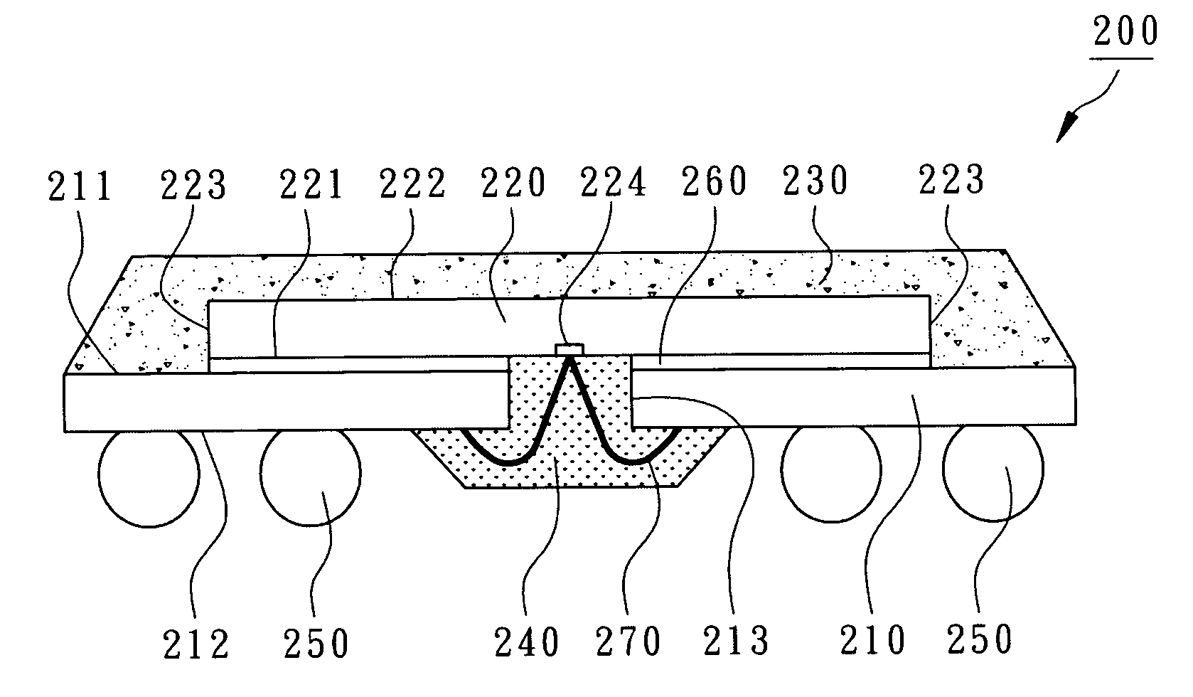
[0028]FIG. 4 to FIG. 8 are shown to illustrate the first embodiment according to the present invention. As shown in FIG. 4 and FIG. 8, an IC package 200, which may be a window BGA, includes a substrate 210, a chip 220, a protective encapsulant 230, at least a stiffening encapsulant 240, and a plurality of external terminals 250. The substrate 210 is an IC carrier with patterned electrical circuits. Normally, the substrate 210 is a printed circuit board or a flexible electrical thin film. The substrate 210 has a top surface211, a bottom surface 212, and at least a slot 213 where the top surface 211 is designed for die attachment and the bottom surface 212 is designed for external electrical mounting. The slot 213 is in a strip penetrating through the top surface 211 and the bottom surface 212. In the present embodiment, as shown in FIG. 5 and FIG. 6, the substrate 210 is approximately rectangular and has a defined long central axis 214. The slot 213 is aligned with the central line 2...
third embodiment
[0038]According to the present invention, an anti-warpage chip carrier for an IC package is revealed, as shown in FIGS. 11 and 12. Before assembly, an anti-warpage chip carrier includes a substrate 410 and at least a rigid stiffener 430 where the substrate 410 has a top surface 411, a bottom surface 412, and at least a slot 413, 414. In the present embodiment, the slot 413 is formed at the center of the substrate 410 and two slots 414 are formed at the edges of the substrate 410. A plurality of bumping pads 415 are formed on the top surface 411 of the substrate 410 and a plurality of ball pads 416 are formed on the bottom surface 412 of the substrate 410 where the bumping pads 415 are electrically connected to the ball pads 416 by internal circuits. In the present embodiment, the substrate 410 is flexible.
[0039]The rigid stiffeners 430 are in a strip and is embedded in the slots 413, 414. The Young's modulus of the rigid stiffener 430 is between 20 GPa and 50 GPa. The material of th...
PUM
 Abstract
Description
Claims
Application Information
 - R&D
- Intellectual Property
- Life Sciences
- Materials
- Tech Scout
- Unparalleled Data Quality
- Higher Quality Content
- 60% Fewer Hallucinations
Browse by: Latest US Patents, China's latest patents, Technical Efficacy Thesaurus, Application Domain, Technology Topic, Popular Technical Reports.
© 2025 PatSnap. All rights reserved.Legal|Privacy policy|Modern Slavery Act Transparency Statement|Sitemap|About US| Contact US: help@patsnap.com


