Heavy duty trailing arm suspension system

a trailing arm and suspension system technology, applied in the direction of resilient suspensions, interconnection systems, vehicle components, etc., can solve the problems of rod configuration, plate lack of structural integrity as an upper attachment member, and difficulty in installation and servi

Inactive Publication Date: 2005-07-28
ARVINMERITOR TECH
View PDF15 Cites 13 Cited by
  • Summary
  • Abstract
  • Description
  • Claims
  • Application Information

AI Technical Summary

Benefits of technology

[0007] The present invention provides a heavy duty suspension system including a frame and a pair of spaced apart trailing arms. The trailing arms each include a forward portion pivotally supported by the frame and extending longitudinally to a rearward portion. An axle has opposing end portions pivotally supported respectively on the trailing arms. A V-rod includes first and second spaced apart ends extending to a common third end with the first and second ends preferably pivotally attached to the frame. The third end is preferably pivotally attached to the axle. The V-rod provides lateral stability and defines a pinion angle with the trailing arms. Preferably, the longitudinal length of the V-rod, and a length of the trailing arm measured from the pivotal attachment on the frame to the pivotal attachment on the axle, are of equal length to provide a constant pinion angle during movement of the suspension system.

Problems solved by technology

Such a configuration of rods has the undesirable effect of moving the axle input shaft along an arcuate path in a vertically lateral plane during suspension operation.
However, the plate lacks sufficient structural integrity as an upper attachment member and is difficult to install and service.
Supporting an anti-roll bar by a frame for heavy duty vehicle applications is not practical since the suspension components may be spaced a significant distance from the frame so that a portion of the frame may not be located sufficiently close to the anti-roll bar.
Accordingly, it is difficult to isolate any one bushing to optimize the roll characteristics.

Method used


Image

  • Heavy duty trailing arm suspension system
  • Heavy duty trailing arm suspension system
  • Heavy duty trailing arm suspension system

Examples


Embodiment Construction

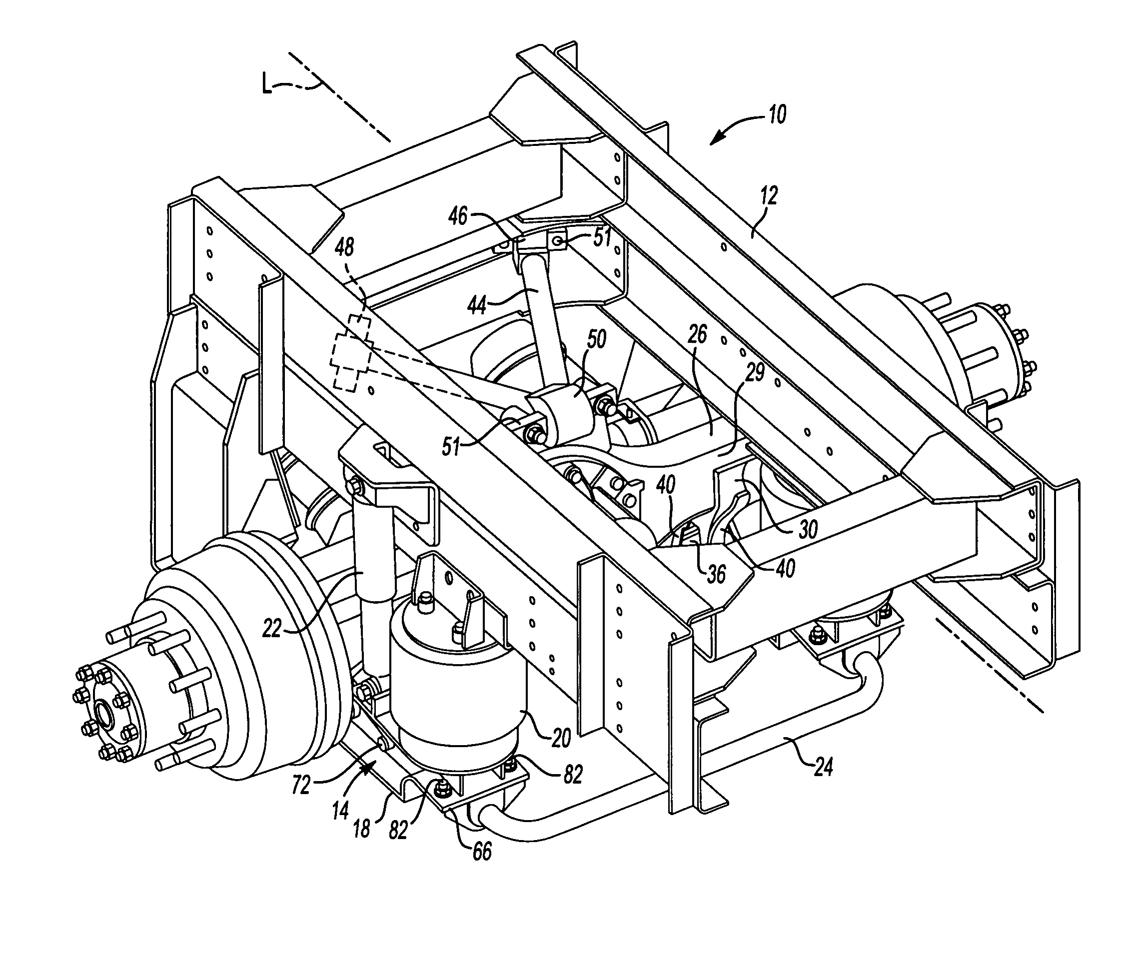
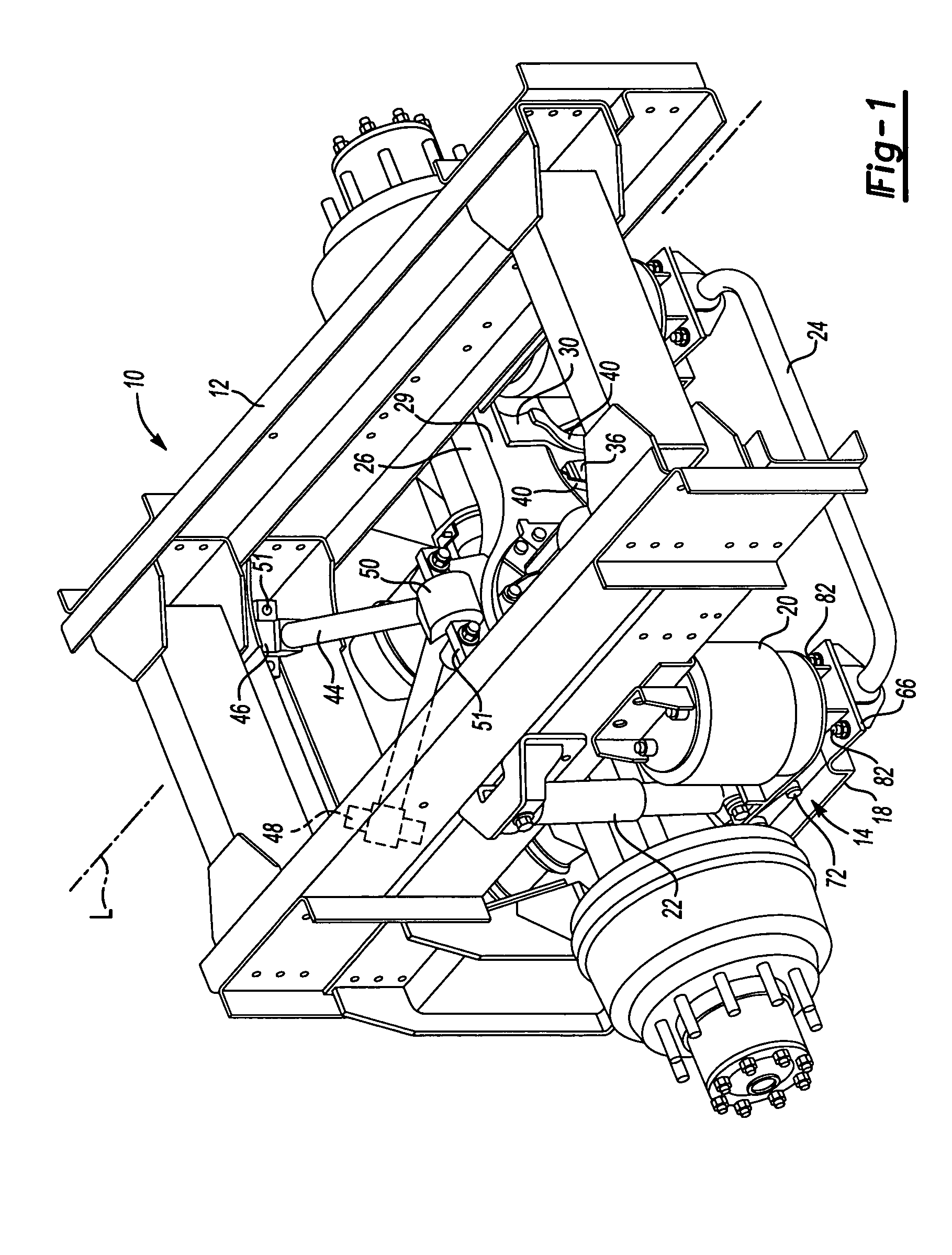
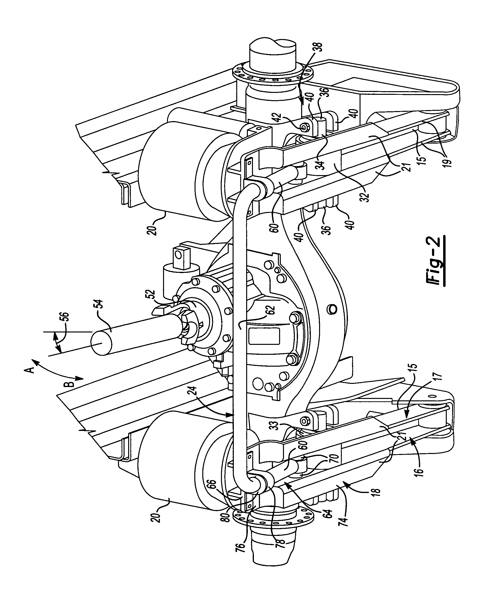
[0013] A suspension system 10 is shown in FIGS. 1 and 2. The system 10 includes a frame 12 that may include longitudinal rails, brackets, and other structural members secured by welds, fasteners or other attachment means. The suspension system 10 includes a pair of spaced apart trailing arms 14. The trailing arms 14 are preferably formed of a rather thick metal forming having opposing sides 19 and an upper wall 15 adjoining the opposing sides 19 to form an inverted U-shape. The lower side 16 has spaced apart flanges 21 extending outwardly from the opposing sides 19 and provides an opening forming a channel 64, as best shown in FIG. 2.

[0014] The trailing arms 14 include a forward portion 17 pivotally attached to the frame 12 and extending longitudinally rearward to a rearward portion 18. Air springs 20 and shock absorbers 22 may be arranged between the trailing arms 14 and the frame 12. An anti-roll bar 24 may be removably secured between the trailing arms 14 to provide stability to...


PUM


Abstract

The present invention provides a heavy duty suspension system including a frame and a pair of spaced apart trailing arms. The trailing arms have at least a portion with an open bottom and flanges extending away from the opening. The trailing arm preferably has a generally U-shaped cross-section over a substantial portion of its length. An axle has opposing end portions pivotally supported respectively on the trailing arms. A V-rod includes first and second spaced apart ends extending to a common third end with the first and second ends preferably pivotally attached to the frame. The third end is preferably pivotally attached to the axle. The V-rod provides lateral stability and defines a pinion angle with the trailing arms. The trailing arms extend longitudinally from the forward portion to a rearward portion. An anti-roll bar includes opposing end portions and a central portion transverse to and extending between the end portions. The end portions are respectively arranged longitudinally along a portion of the trailing arms and are pivotally secured respectively to the trailing arms.

Description

[0001] This application is a Continuation-In-Part of U.S. Ser. Nos. 10 / 194,780 and 10 / 194,817, both of which were filed on Jul. 12, 2002.BACKGROUND OF THE INVENTION [0002] This invention relates to a heavy duty suspension system, and more particularly, the invention relates to a trailing arm suspension system. [0003] Various types of suspension configurations have been used for heavy duty applications. For drive axles, the suspension geometry affects a pinion angle. The pinion angle is the angle between an axle input shaft axis and a drive shaft axis. It is desirable to have as little pinion angle as possible to reduce wear. Additionally, it is desirable to have equal angles for the drive shaft axis and the axle input shaft axis and the transmission output shaft axis to balance the forces on the yokes. [0004] Trailing arm suspensions have been employed for heavy duty applications, such as for motorhomes. An axle may be rigidly or pivotally secured to the trailing arm. For drive axle...

Claims


Application Information

Patent Timeline
Patent Type & Authority Applications(United States)
IPC IPC(8): B60G3/12
CPCB60G9/022B60G2204/1222B60G2200/315B60G21/0551
Inventor REINECK, BENJAMIN R.
Owner ARVINMERITOR TECH
Why Eureka
Try Eureka