
Centrifugal blower

a centrifugal blower and centrifugal technology, applied in the direction of wind motors with parallel air flow, wind motors with perpendicular air flow, liquid fuel engine components, etc., can solve the problems of less efficiency, performance and/or noise of conventional one-piece impellers, and produce relatively low pressur

Active Publication Date: 2005-07-28
ROBERT BOSCH CORP
View PDF13 Cites 69 Cited by
  • Summary
  • Abstract
  • Description
  • Claims
  • Application Information

AI Technical Summary

Problems solved by technology

In some instances, the high flow resistance during heater and defrost modes can cause performance and / or noise problems for conventional one-piece impellers, which may be less efficient than the more expensive two-piece impellers, or only capable of producing relatively low pressures compared to the more expensive two-piece impellers.

Method used


Image

  • Centrifugal blower
  • Centrifugal blower
  • Centrifugal blower

Examples


Embodiment Construction

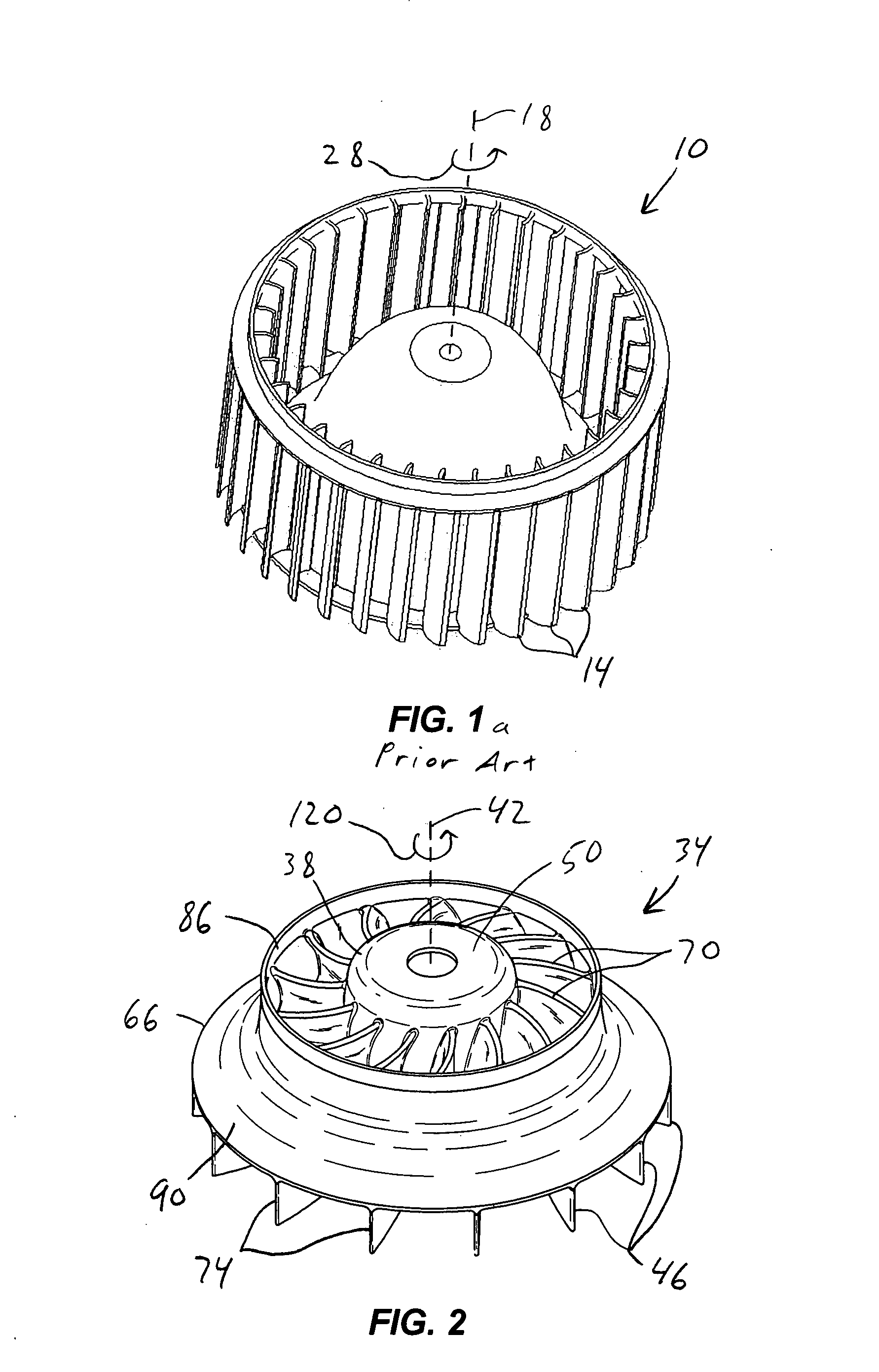
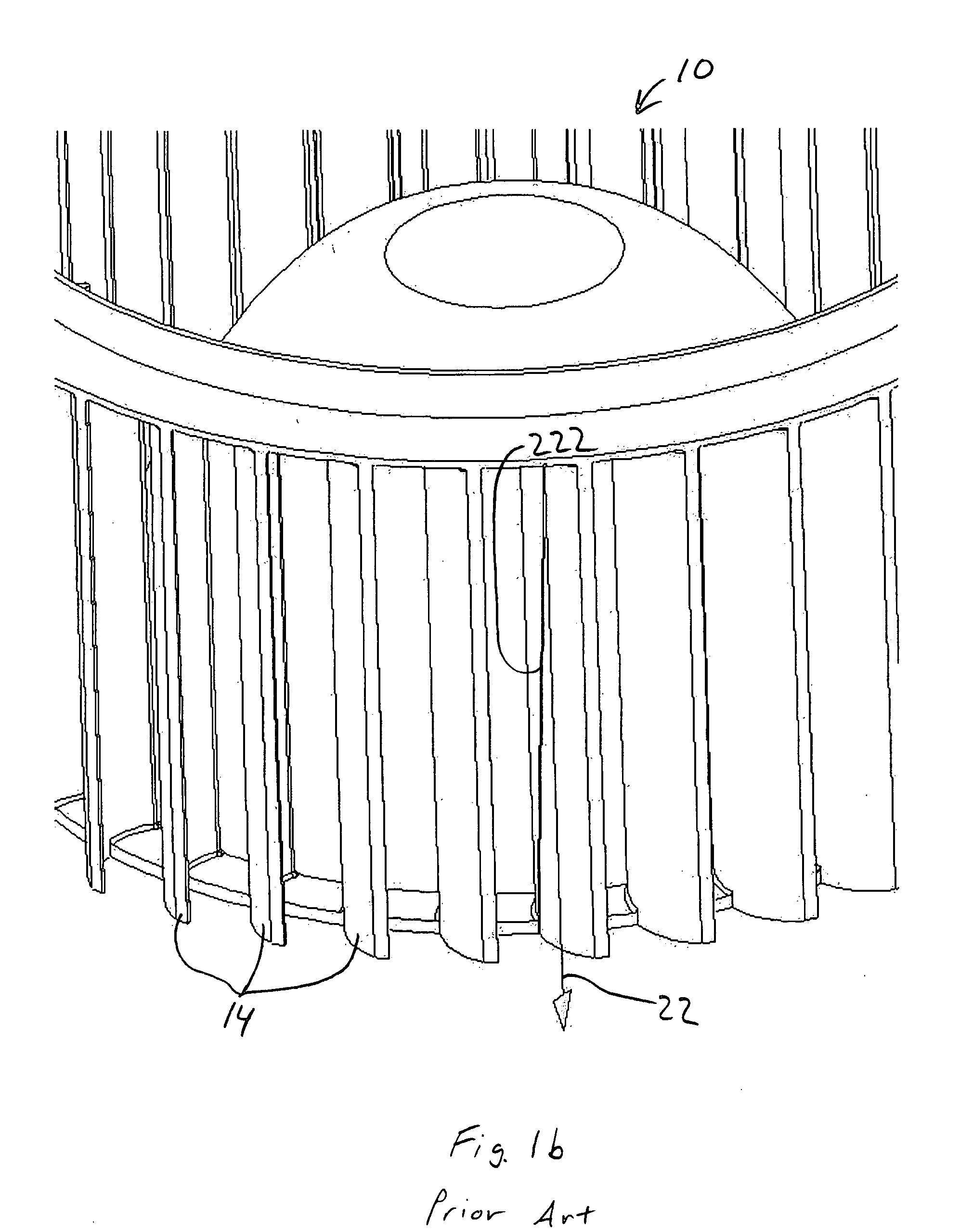
[0038]FIG. 1a illustrates a typical prior-art, one-piece, forward-curved fan 10. The fan 10 includes a plurality of blades 14 that are formed from a two-dimensional curve. In other words, the only curvature of the blades 14 occurs in a plane that is taken through the blades 14 and that is normal to a rotational axis 18 of the fan 10. The fan 10 is typically manufactured from a plastic material using a molding process (e.g., an injection molding process). The two-dimensional blade forms allow the fan 10 to be molded as one piece using a relatively simple mold separated into two mold halves which may be brought together or separated from one another along a mold axis 22 (see FIG. 1b). The parting line on the surface of the blades 14 is substantially parallel to the mold axis 22.

[0039]FIG. 1c illustrates a typical prior art, two-piece, backward-curved fan 300. The fan 300 includes a plurality of blades 304 that are formed from a two-dimensional curve. In other words, the only curvatur...


PUM


Abstract

The present invention provides a centrifugal fan including a hub adapted for rotation about a central axis and a plurality of blades arranged about the central axis and coupled for rotation with the hub. Each of the blades includes a curvature in a plane that extends through the blade and is tangent to a cylinder which extends through the blade and is centered along the central axis.

Description

FIELD OF THE INVENTION [0001] This invention relates generally to centrifugal blowers, and more particularly to centrifugal blowers for use in automotive climate control systems. BACKGROUND OF THE INVENTION [0002] Centrifugal blowers typically include impellers having a plurality of blades that redirect an incoming airflow toward a radial direction as the airflow moves from the impeller inlet to the impeller outlet. The blades are typically attached to a hub for rotation therewith. The hub typically defines an airflow surface on the base of the impeller to help redirect the incoming airflow. [0003] In automotive climate control applications (i.e., heating, ventilation, and air conditioning), centrifugal impellers may be generally grouped into two categories: a) low cost, one-piece impellers; and b) higher cost, higher efficiency, two-piece impellers. One-piece impellers, because of their lower cost, are generally more prevalent in automotive climate control applications than two-pie...

Claims


Application Information

Patent Timeline
Patent Type & Authority Applications(United States)
IPC IPC(8): F04D29/28F04D29/30
CPCF04D29/30F04D29/284F04D29/281F04D29/162F04D29/403F04D29/441F04D29/023F04D29/5806H02K9/06F05D2210/12Y10S416/00Y10S415/00
Inventor CHAPMAN, THOMAS R.
Owner ROBERT BOSCH CORP
Learn More