Centrifugal fan with improved air cooling for its motor, especially for a motor vehicle

a centrifugal fan and motor technology, applied in the direction of motors, dynamo-electric machines, electrical apparatus, etc., can solve the problems of difficult cooling of motors and unsatisfactory arrangement, and achieve the effect of improving the effectiveness of diversion of air, facilitating connection, and optimising operation

Inactive Publication Date: 2000-03-07
VALEO SYST THERMIQUES
View PDF8 Cites 38 Cited by
  • Summary
  • Abstract
  • Description
  • Claims
  • Application Information

AI Technical Summary

Benefits of technology

In addition, with a view to improving even more the effectiveness of the diversion of air for cooling purposes, the second predetermined zone is arranged in an upper region of the casing, substantially above the fan rotor. This enables advantage to be taken of the suction induced by rotation of the rotor, and this consequently optimises the operation of taking off air for diversion.
In a preferred embodiment of the invention, the said predetermined first zone comprises a portion of the casing outer wall, or side wall portion, which is formed with the diversion ports in the form of through holes, and defines an elbow in the region of the junction between the inlet end and delivery end of the volute, and this elbow is closed by a complementary wall in

Problems solved by technology

Due to its position within the casing of the fan, it is difficult to cool the motor.
However, this arrangement is not entirely satisfactory, partly because it does not en

Method used


Image

  • Centrifugal fan with improved air cooling for its motor, especially for a motor vehicle
  • Centrifugal fan with improved air cooling for its motor, especially for a motor vehicle
  • Centrifugal fan with improved air cooling for its motor, especially for a motor vehicle

Examples


Embodiment Construction

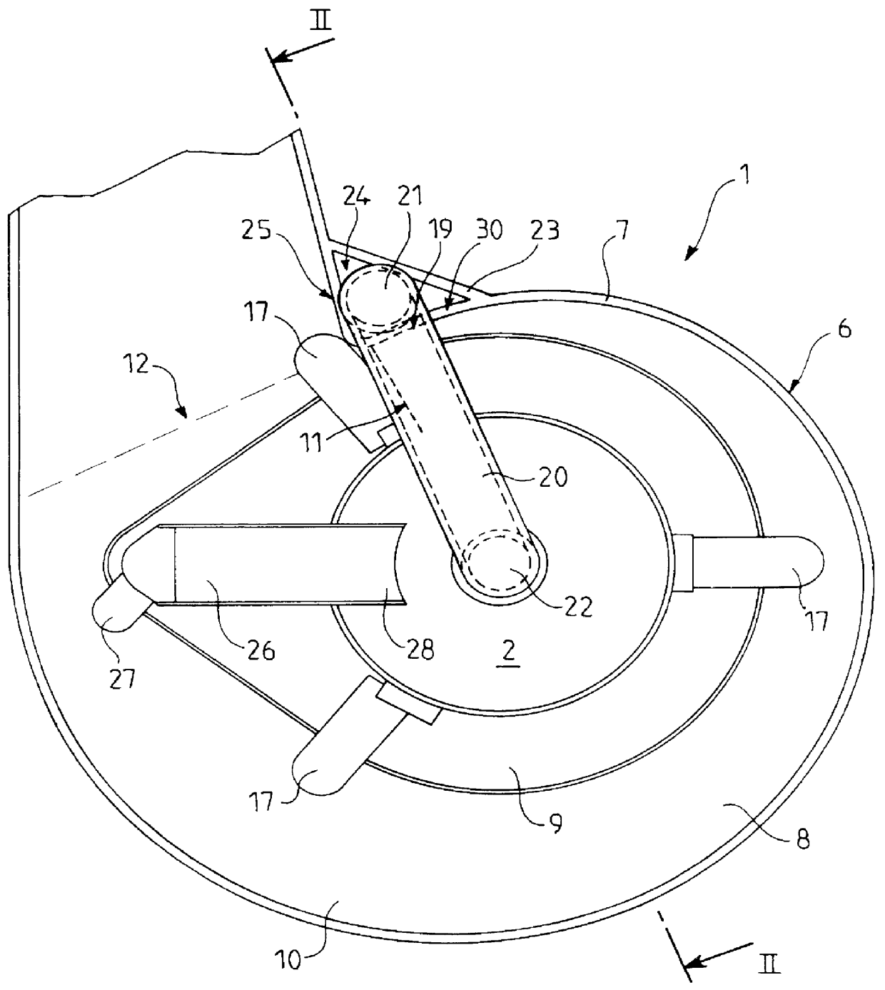
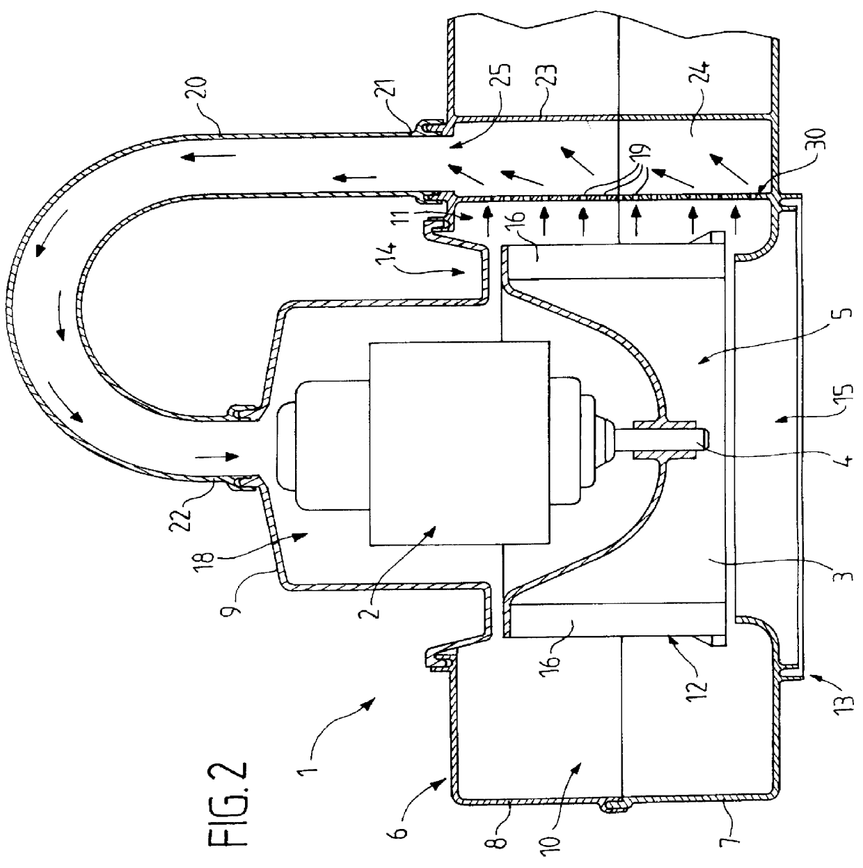
Reference is first made to FIGS. 1 and 2, which show a centrifugal fan 1 which is for example intended to deliver blown air to an air distribution and treatment unit in a heating and / or air conditioning installation for a motor vehicle.

The centrifugal fan 1 has a casing 6 and comprises an electric motor 2 which drives a fan rotor 3 in rotation about an axis of revolution defined by a motor shaft 4, which then defines the longitudinal direction of the fan. The electric motor 2 is controlled by a control module (not shown) which governs the level of voltage or current supplied to the motor, and which in consequence controls the speed of rotation of the fan rotor 3.

The electric motor 2 and the fan rotor 3 are mounted in a central region 5 of the casing 6, the outer wall of which partly defines a spiral volute 10. The cross section of the volute 10 increases from its inlet end 11 to its delivery end 12. The volute 10 extends around the central region 5 of the casing, and is in fact boun...


PUM


Abstract

A centrifugal fan for a motor vehicle has a fan rotor driven in rotation by an electric motor and lodged in a central part of a casing. The outer walls of the casing define, in conjunction with a peripheral portion of the rotor, a volute for channeling air which is delivered by the rotor in a tangential direction. The outer wall of the casing includes a longitudinal side wall portion formed with through apertures constituting diversion ports, for taking off some of the air delivered by the rotor and diverting this air through an external duct fixed to the casing and open into the central region of the latter, so as to cool the motor.

Description

This invention relates to centrifugal fans, in particular for motor vehicles. More particularly, the invention relates to centrifugal fans of the type comprising a fan rotor which is driven in rotation by an electric motor and mounted in a central region of a casing, with the outer wall of the casing, together with the periphery of the fan rotor, defining a volute for channeling air which is delivered by the fan rotor in a direction tangential to the periphery of the latter.In operation, the motor of such a fan becomes heated. Due to its position within the casing of the fan, it is difficult to cool the motor. In order to overcome this drawback, it has been proposed to equip the casing with a duct for diverting some of the air within the volute, and more particularly into an upper part of the latter, so as to pass it close to the motor. However, this arrangement is not entirely satisfactory, partly because it does not enable enough air to be diverted, and secondly because it gives r...

Claims


Application Information

Patent Timeline
IPC IPC(8): F04D25/02F04D25/08F04D29/42
CPCF04D25/082F04D29/422F04D29/5806
Inventor EL MAYAS, JIHAD
Owner VALEO SYST THERMIQUES
Why Eureka
Try Eureka