Brushless cooling fan

a technology of brushless direct current and fan blades, which is applied in the direction of positive displacement liquid engines, piston pumps, liquid fuel engines, etc., can solve the problems of inability to meet the needs of control electronics, inability to overcome mechanical wear and subsequent need, and inability to meet the needs of potentially less rugged and complex control electronics, etc., to achieve high efficiency, keep the resistance low, and the effect of high efficiency

Active Publication Date: 2012-08-28
PAIRAKTARIDIS JOHN
View PDF29 Cites 39 Cited by
  • Summary
  • Abstract
  • Description
  • Claims
  • Application Information

AI Technical Summary

Benefits of technology

[0017]It is a further object of the invention to produce a brushless motor cooling fan with a high efficiency brushless direct current motor (BLDC). Accordingly, the invention is a brushless motor cooling fan with a plurality of air ducts through a BLDC, the air ducts drawing a cooling airflow from a static lower pressure of a rotating impeller through a plurality of ducts in a shroud hub, cooling the BLDC, keeping the resistance low for high efficiency.
[0018]It is yet a further object of the invention to produce a brushless motor cooling fan with a rugged brushless direct current (BLDC) motor that has a rotor that is cooled by air. Accordingly, the invention is a brushless motor cooling fan with a BLDC motor with a centrifugal fan and a plurality of skewed magnets inside the motor, drawing cooling air through the BLDC and cooling the BLDC, improving the efficiency, durability and ruggedness by lowering the temperature of BLDC during operation.

Problems solved by technology

However, brushed DC motors are inefficient and prone to mechanical failure.
Brushless direct current (BLDC) motors overcome the lower efficiency, susceptibility to mechanical wear and consequent need for servicing, the characteristic limitations of brushed DC motors.
Brushless motors are more desirable than a conventional brushed motor, but come at the cost of potentially less rugged and more complex and expensive control electronics.
These control electronics are not well suited for functioning under the hood of an automobile, where high temperatures generated by the engine create a hostile environment for the complex and expensive electronics.
This limits the reliability of an electronic control system, and consequently, the BLDC motor in high temperature environments.
The higher cost, increased complexity and limited reliability at high temperatures have curtailed the adaptation of BLDC components in under-the-hood automotive applications.
Modern automobiles with more powerful engines paradoxically need both an efficient, powerful, and reliable cooling system and generate relatively high temperatures hostile to BLDC electronic control systems.
High temperatures increase electrical resistance, requiring more electricity to generate the same magnetic field and producing even more heat, creating the potential for thermal runaway, leading to burnout of the coils and destruction of the motor and other critical components.
Similarly, many have thought about balancing wheels or crankshafts on automobiles where wobble is undesirable.

Method used


Image

  • Brushless cooling fan
  • Brushless cooling fan
  • Brushless cooling fan

Examples


Embodiment Construction

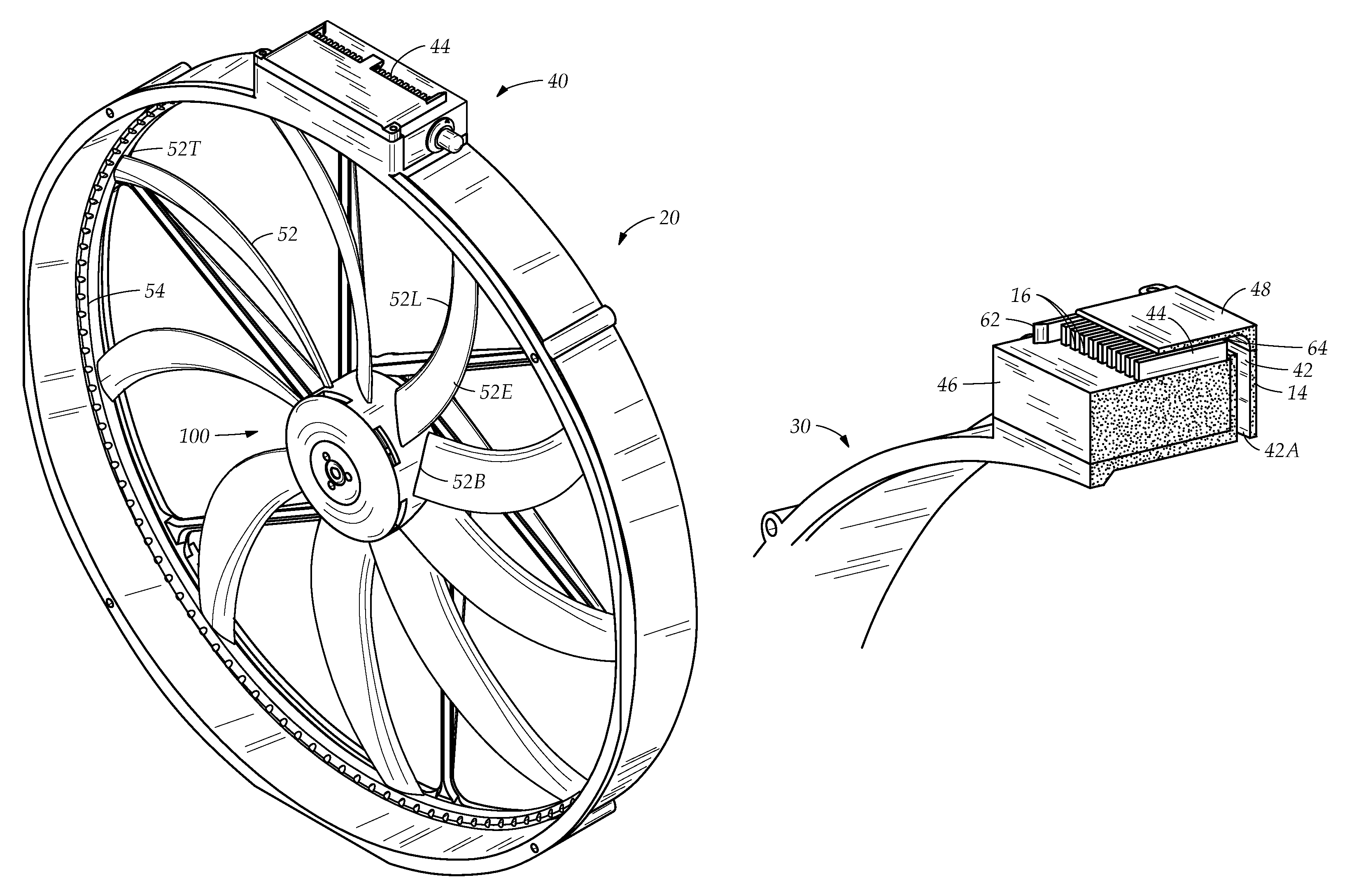
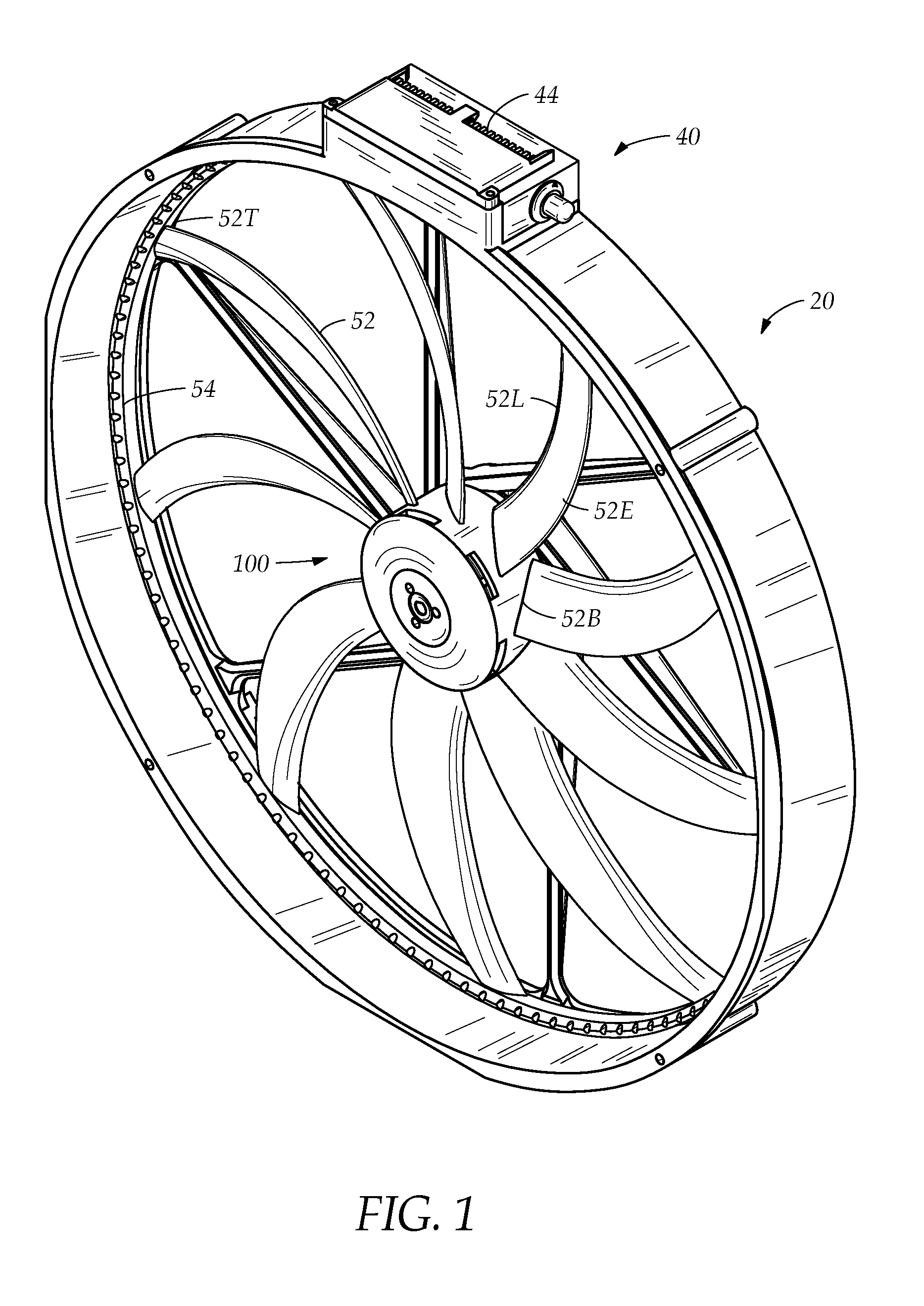
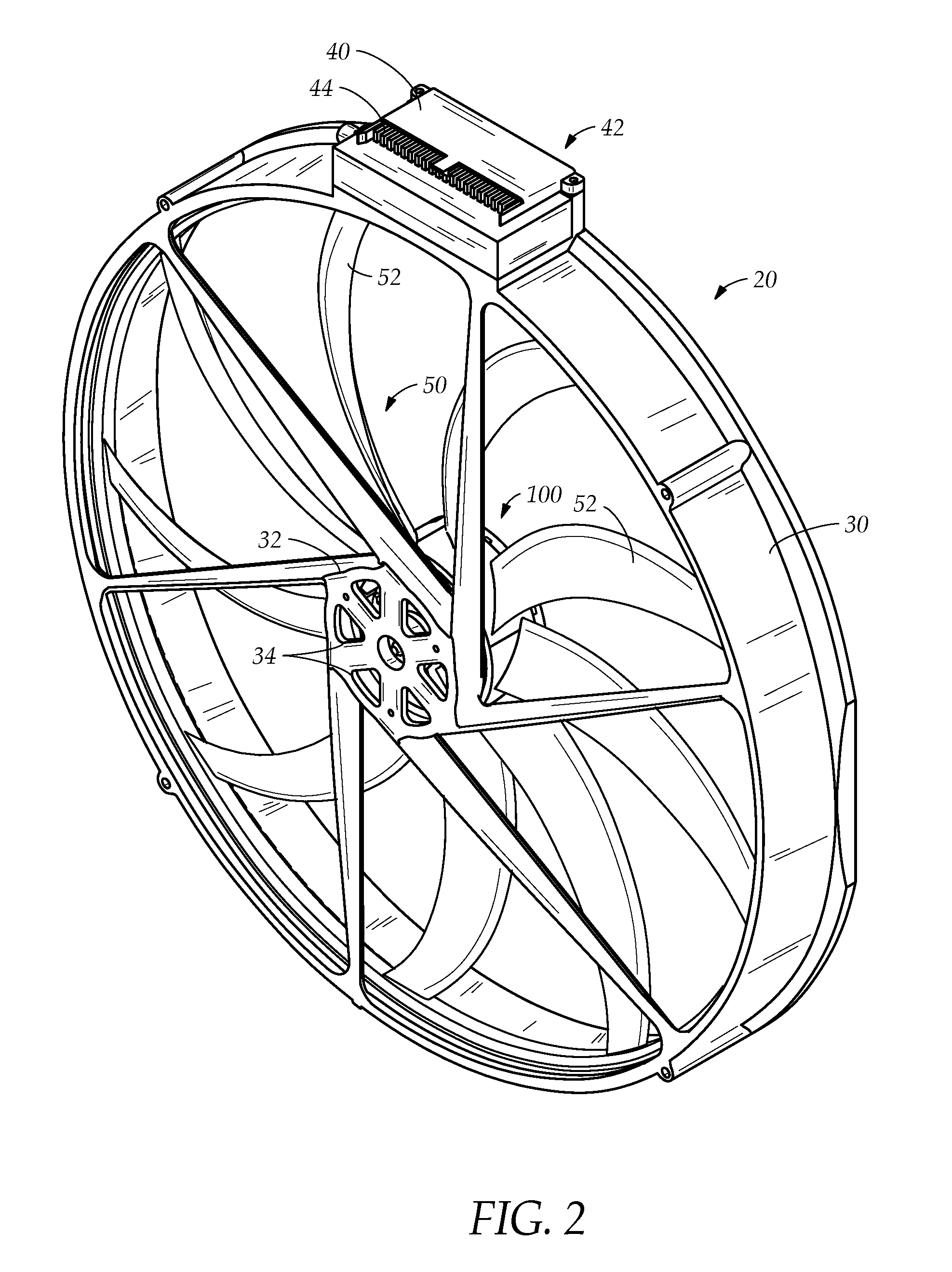
[0036]FIG. 2 illustrates a brushless cooling fan assembly 20 for application in an cooling system of a vehicle with an internal combustion engine. The fan assembly 20 is powered by a high efficiency external rotor brushless direct current (BLDC) motor 100. The form and construction of the fan assembly 20 allows for the efficient and reliable operation of a vehicle cooling system that eliminates the drawbacks of BLDC motors, especially operating in a high temperature environment found under a vehicle hood. This is accomplished by strategic positioning a plurality of critical components and integrating these components with a plurality of air ducts 42, 34 for forced air convection cooling as explained hereinbelow.

[0037]The fan assembly has the open architecture (BLDC) motor 100 with an electronic control module (ECM) 40, an axial fan impeller 50 and a fan shroud 30, each having an innovative structure that promotes cooling of critical electronic components. The cooling fan assembly 20...


PUM


Abstract

A fan assembly with impeller and shroud for application in a vehicle cooling system. The fan is powered by an external rotor brushless direct current (BLDC) motor having an electronic controller positioned away from the BLDC on an outer shroud wall with a plurality of ducts drawing an airflow from a static lower pressure created by the impeller, the airflow streaming over a heat sink disposed on the controller, exiting through a shroud. The static lower pressure air is pulled by a centrifugal fan and skewed magnets inside the motor through a plurality of ducts in a shroud hub, cooling the BLDC, maintaining low resistance for high efficiency. The BLDC is integrated into the assembly, having a stator fixed in the shroud hub and a rotor directly fused to the impeller, the shroud and impeller forming the BLDC motor without a housing, allowing the motor to easily dissipate heat.

Description

CROSS-REFERENCE TO RELATED APPLICATIONS[0001]This application is a continuation application of the nonprovisional utility patent application Ser. No. 13 / 100,437 filed in the United States Patent Office on May 4, 2011 and claims the priority thereof.BACKGROUND OF THE INVENTION[0002]The invention relates generally to a brushless cooling fan. More particularly, the invention relates to a high efficiency brushless motor cooling fan for an automotive application.[0003]Internal combustion engines, automotive engines as a prime example, require cooling. Typical cooling systems involve pumping a coolant over the heat generating systems and pumping the heated fluid to a fan-cooled radiator to release the heat to the atmosphere. Typically, a cooling system uses a brushed direct current (DC) motor to power the system fan. However, brushed DC motors are inefficient and prone to mechanical failure. Brushless direct current (BLDC) motors overcome the lower efficiency, susceptibility to mechanical...

Claims


Application Information

Patent Timeline
Patent Type & Authority Patents(United States)
IPC IPC(8): F04B35/04H02K9/06
CPCH02K9/06H02K11/0073H02K21/22F04D25/0613F04D29/5813H02K5/20H02K7/14H02K11/33H02K5/207
Inventor PAIRAKTARIDIS, JOHN
Owner PAIRAKTARIDIS JOHN
Why Eureka
Try Eureka