In-line centrifugal fan

a centrifugal fan and inline technology, applied in the direction of marine propulsion, vessel construction, other chemical processes, etc., can solve the problems of affecting the service life of the fan, the need to reinstall non-modular moveable parts, and the limited internal drive components of the fan

Inactive Publication Date: 2003-11-06
GREENHECK FAN
View PDF12 Cites 40 Cited by
  • Summary
  • Abstract
  • Description
  • Claims
  • Application Information

AI Technical Summary

Problems solved by technology

Furthermore, servicing conventional fans' internal drive components has typically been limited and cumbersome due to the limited accessibility to their internal drive components, which requires the removal, and disassembly, of other internal components.
Subsequently, the non-modular moveable parts need to be reinstalled within the fan, which is difficult given the small internal confines of the fan.
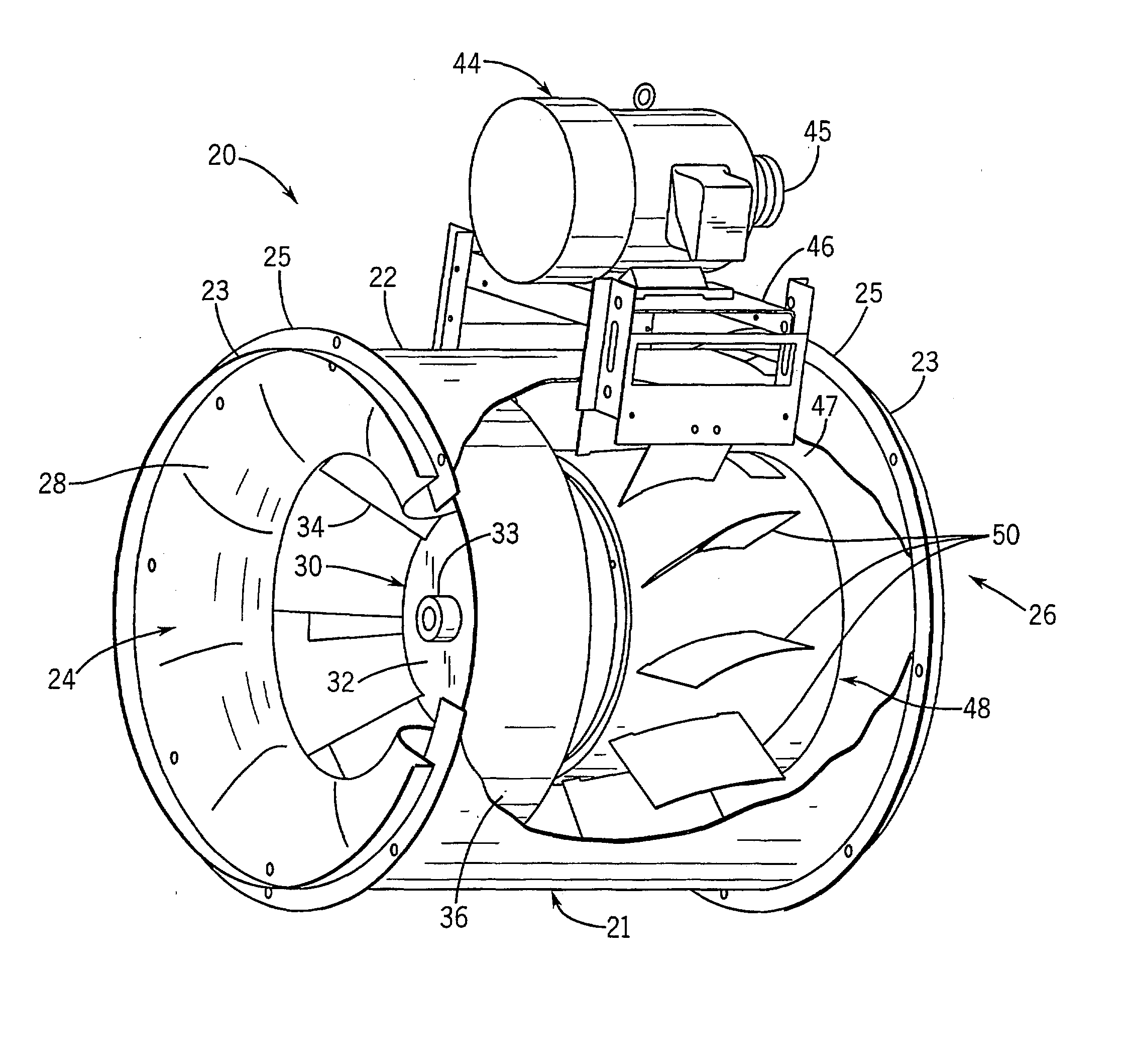
The bearing assembly is removable from the conduit as a unitary assembly, which allows the fan to be easily serviced when access to the fan's internal drive components has been quite limited and cumbersome in conventional inline centrifugal fans.
The straightening vanes 50 are more easily and

Method used


Image

  • In-line centrifugal fan
  • In-line centrifugal fan
  • In-line centrifugal fan

Examples


Embodiment Construction

1" 2" 3" CFM BHP Eff. DBA BHP Eff. DBA BHP Eff. dBA 4100 1.31 49% 67 2.13 61% 69 3.02 64% 70 6100 1.81 53% 69 2.92 66% 70 4.25 68% 72 13200 3.52 59% 70 5.98 69% 72 8.74 71% 74 20000 5.56 57% 74 9.14 69% 75 13.32 71% 76

[0053] Significant advantages are achieved by the present invention, as apparent when comparing Tables 1, corresponding to the prior art, and Table 2, corresponding to the present invention. For example, a fan constructed in accordance with the present invention achieves a reduced brake horsepower needed to achieve the same airflow compared to the prior art, thereby resulting in a significantly greater efficiency. Additionally, the present invention achieves a dramatic reduction in sound levels during operation at any given fan static pressure. For example, when operating at 4100 CFM with a one inch water gauge of fan static pressure, the present invention is 13 percentage points more efficient than the prior art, thereby conserving an appreciable amount of energy and ...


PUM


Abstract

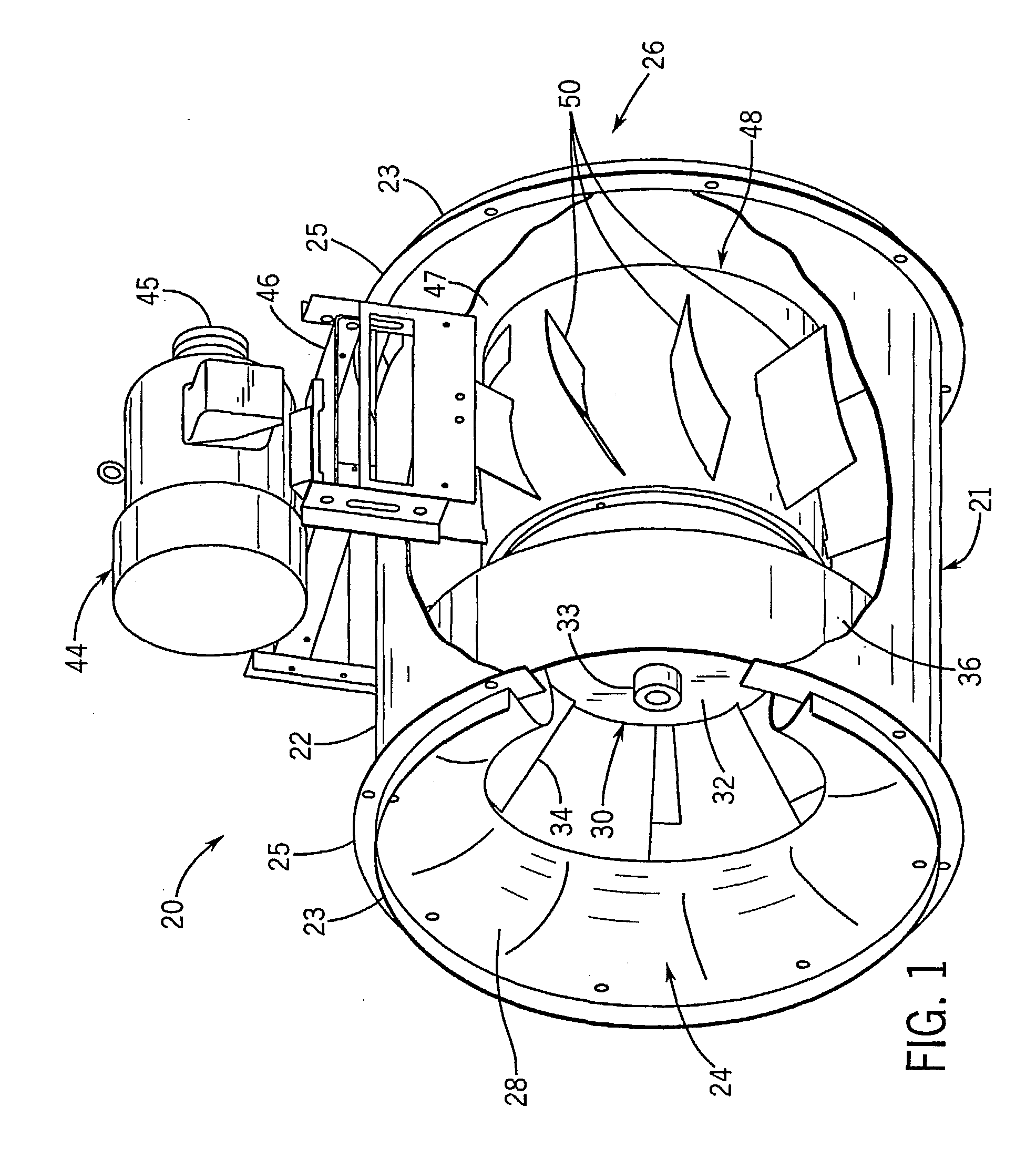
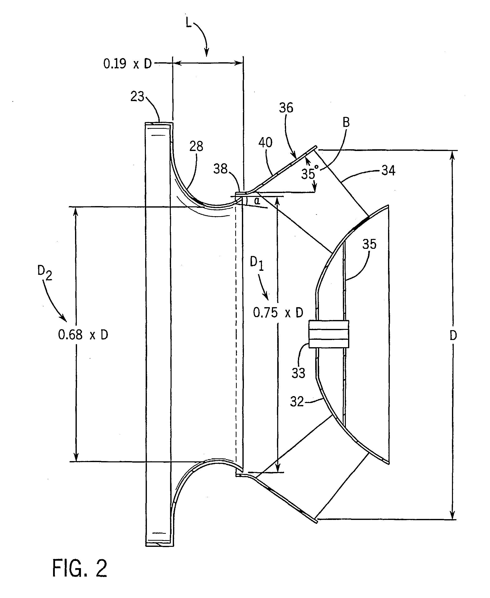
An inline centrifugal mixed flow fan (20) includes an axially extending intake conduit (22). An inlet cone (28) is disposed at an intake end (24). An impeller (30) is disposed downstream of the inlet cone and includes a centrally disposed wheel-back (32) rotated by an electric motor (44), plural fan blades (34) extending radially outwardly from the wheel-back and a wheel cone fixedly (36) attached to and circumscribing the wheel blades. A driver chamber (48) downstream of the impeller includes plural radially extending straight vanes (50) to direct air to an outlet end (26). The fan is configured to achieve reduced sound level and increased efficiency.

Description

[0001] This application claims the benefit provisional U.S. application Ser. No. 60 / 211,741, entitled "In-Line Centrifugal Fan" which was filed on Jun. 15, 2000, the disclosure of which is hereby incorporated by reference as if set forth in its entirety herein.[0002] Not applicable.[0003] The present invention relates generally to an in-line centrifugal fan, and in particular, relates to a mixed flow fan having a high operating efficiency and reduced sound output, and that is easy to manufacture and service.[0004] In-line fans are generally classified according to the direction of airflow through the impeller. In particular, axial flow fans are characterized by flow through the impeller in a direction generally parallel to the shaft axis. In-line centrifugal fans receive airflow into the impeller axially, and redirect the airflow radially outward. Mixed flow fans are characterized in that the air enters the impeller axially and is deflected at an obtuse angle by the impeller blades ...

Claims


Application Information

Patent Timeline
IPC IPC(8): F04D17/06F04D17/16F04D29/30
CPCF04D17/06Y10S416/02F04D29/30F04D17/165
Inventor MATHSON, TIMOTHY R.KUSKI, TIMOTHY D.
Owner GREENHECK FAN
Why Eureka
Try Eureka