Artificial disc replacement (ADR) fixation methods and apparatus

a technology of artificial discs and fixation methods, applied in the field of artificial disc replacement, can solve the problems of reducing the efficiency of disc degeneration surgery, reducing the ability of the nucleus to handle compression load, and reducing the effectiveness of redundant annular fibers in controlling vertebral motion, so as to improve the fit of the patient's vertebrae and facilitate the bending of the adr

Inactive Publication Date: 2005-07-28
FERREE BRET A
View PDF26 Cites 96 Cited by
  • Summary
  • Abstract
  • Description
  • Claims
  • Application Information

AI Technical Summary

Benefits of technology

[0009] The present invention improves upon prior-art ADRs, including ADRs with plate-like extensions, in several respects. First, the ADR can be bent at the junction of the plate-l

Problems solved by technology

The nucleus becomes thinner and less able to handle compression loads.
The redundant annular fibers are less effective in controlling vertebral motion.
Current surgical treatments of disc degeneration are destructive.
These destructive procedures lead to acceleration of disc degeneration.
The first two groups of procedures compromise the treated disc.
The additional stress results in p

Method used


Image

  • Artificial disc replacement (ADR) fixation methods and apparatus
  • Artificial disc replacement (ADR) fixation methods and apparatus
  • Artificial disc replacement (ADR) fixation methods and apparatus

Examples


Embodiment Construction

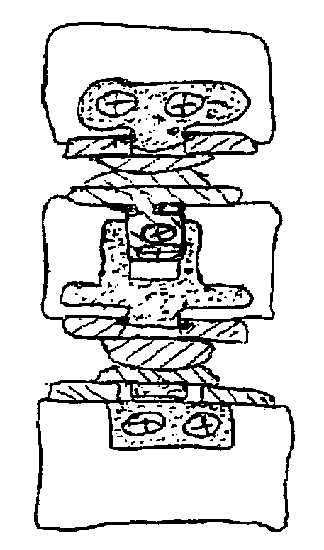
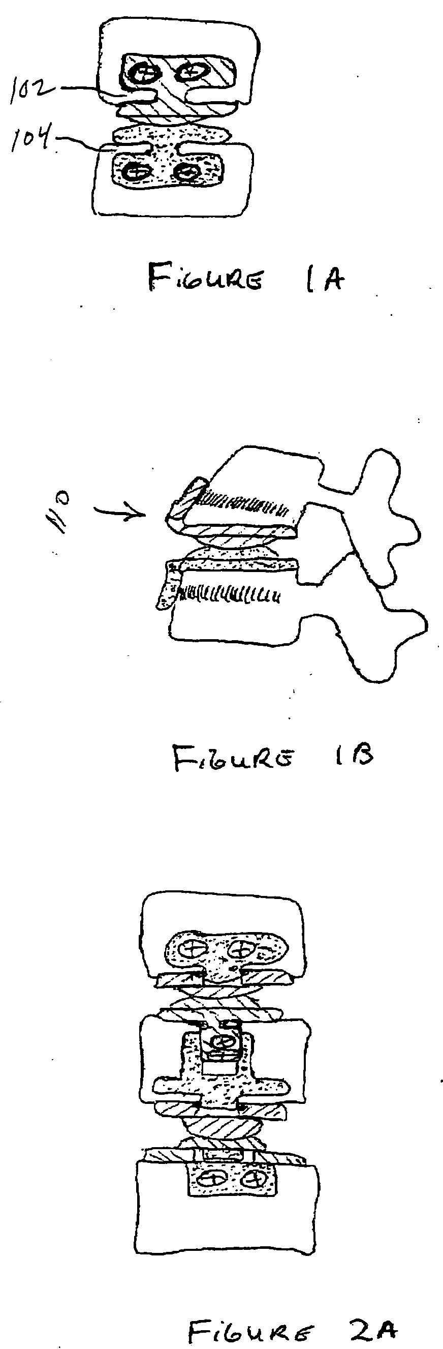
[0069]FIG. 1A is an anterior view of an ADR according to the invention and two vertebrae. The narrow areas 102, 104 connect the plate-like components to the ADR EPs facilitates bending the ADR. The screws can be locked into the ADR by C-rings incorporated in the plate-like components. The thin area of the TDR EP, between the intradiscal component and the component on the anterior surface of the vertebra, could be transected. Cutting the TDR EP allows removal of the extradiscal component during revision surgery. Removing the extradiscal component facilitates placement of a TDR at an adjacent level during a subsequent surgery. Alternatively, the strip of metal between the intradiscal and extradiscal components could be replaced with one or more cables. FIG. 1B is a partial sagittal view of the spine and the embodiment of the ADR drawn in FIG. 1A. Note that the upper ADR component 110 has bent to better fit the anterior surface of the vertebra.

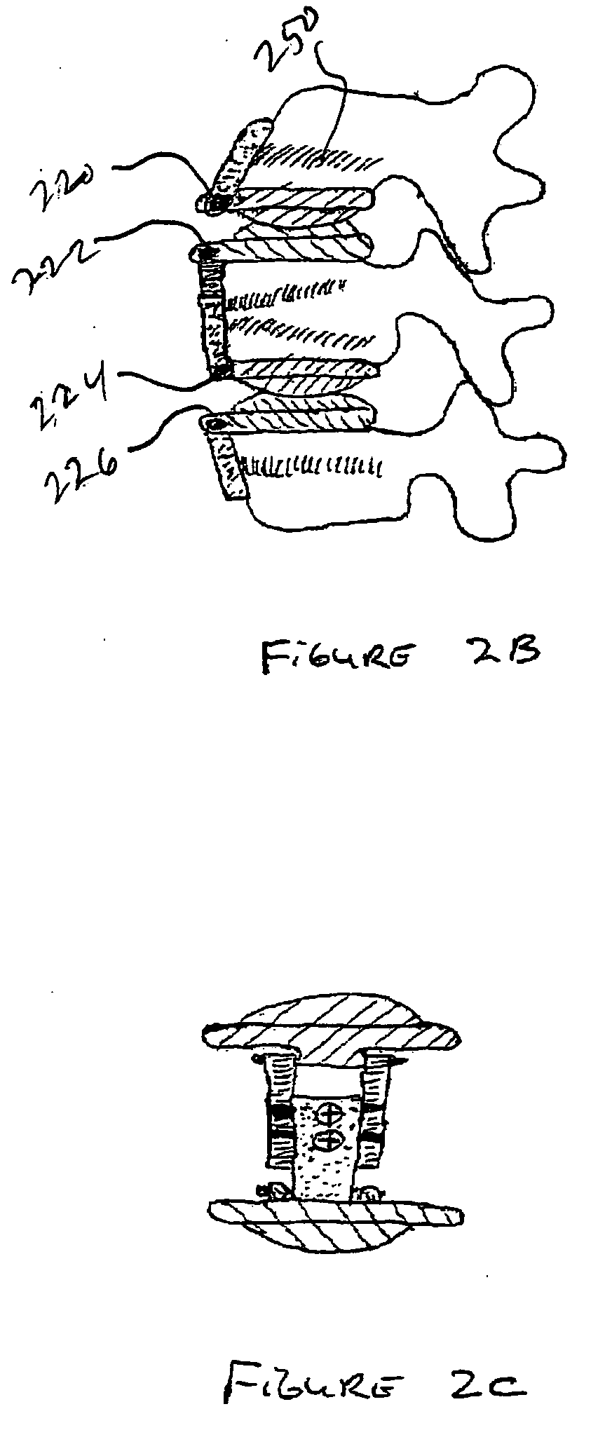
[0070]FIG. 2A is an anterior view of the ...


PUM


Abstract

Artificial disc replacements (ADRs), including ADRs with plate-like extensions, can be bent at the junction of the plate-like extension and the ADR Endplate (EP), which allows customization of the ADR to better fit a patient's vertebrae. A hinge joint allows customization of the ADR to fit a patient's vertebrae better. Other embodiments of the ADR contain telescoping components which allow customization of ADRs to replace two or more adjacent discs. Plate-like extensions that inter-digitate facilitate ADR insertion at two or more adjacent levels of the spine. Mechanisms to prevent screws from backing out of the plate-like projections are also disclosed. Nitinol or other shape-memory materials may be used for such purpose. Various other anti-back-out and anti-extrusion mechanisms are disclosed, all of which are applicable to non-spine applications, including long-bone plates, and total hip, knee and other joint prostheses.

Description

REFERENCE TO RELATED APPLICATION [0001] This application claims priority from U.S. Provisional Patent Application Ser. No. 60 / 538,179, filed Jan. 22, 2004, the entire content of which is incorporated herein by reference.FIELD OF THE INVENTION [0002] This invention relates generally to artificial disc replacement (ADR) and, in particular, to fixation methods and apparatus therefore. BACKGROUND OF THE INVENTION [0003] Premature or accelerated disc degeneration is known as degenerative disc disease. A large portion of patients suffering from chronic low back pain are thought to have this condition. As the disc degenerates, the nucleus and annulus functions are compromised. The nucleus becomes thinner and less able to handle compression loads. The annulus fibers become redundant as the nucleus shrinks. The redundant annular fibers are less effective in controlling vertebral motion. The disc pathology can result in: 1) bulging of the annulus into the spinal cord or nerves; 2) narrowing o...

Claims


Application Information

Patent Timeline
IPC IPC(8): A61B17/00A61B17/80A61B17/86A61B17/88A61F2/00A61F2/30A61F2/44A61F2/46
CPCA61B17/8033A61F2250/0097A61B17/8052A61B17/86A61B17/8625A61B17/8875A61B2017/00867A61F2/4425A61F2/4657A61F2002/30092A61F2002/30179A61F2002/30462A61F2002/30471A61F2002/30485A61F2002/30495A61F2002/30499A61F2002/30507A61F2002/30517A61F2002/30525A61F2002/30551A61F2002/30565A61F2002/30578A61F2002/30601A61F2002/30617A61F2002/30774A61F2002/30841A61F2002/30884A61F2002/449A61F2002/4663A61F2210/0014A61F2220/0025A61F2220/0075A61F2220/0091A61F2230/0058A61B17/8042A61F2002/3055
Inventor FERREE, BRET A.
Owner FERREE BRET A
Why Eureka
Try Eureka