Lattice tower disguised as a monopole

a technology of monopoly and lattice tower, which is applied in the direction of wind energy generation, structural elements, building components, etc., can solve the problems of few solutions of acceptable cost levels (if any) for monopoles, the larger the cost difference between a lattice tower solution and a monopole solution, and the capacity of most known in the art monopole solution to conceal feeder cables within their cross-section is still limited

Inactive Publication Date: 2005-08-04
SILBER MEIR
View PDF5 Cites 112 Cited by
  • Summary
  • Abstract
  • Description
  • Claims
  • Application Information

AI Technical Summary

Benefits of technology

[0028] It is the aim of the present invention is to provide an efficient solution for a tower that would combine the load bearing capacity and cost effectiveness of a metal lattice tower with the aesthetic advantages generally attributed to monopoles. The heart of the invention is the basic concept of separation between the structurally functioning elements, which are kept concealed, and a non-structural shell which provides the tower the shape of a monopole.
[0031] According to another embodiment of the present invention, the entire height of said shell is divided, for fabrication and assembly purposes, into a plurality of separable shell sections respectively, each having transportable dimensions, such that each shell section is directly fastened to at least one of said metal rings, and the joint between every two adjacent said shell sections, once finally assembled, is made such that the bottom end of the upper of said sections is extending over the top end of the lower of said sections, so that a relatively small overlap exists there between, allowing vertical slip of the interior surface of the upper section relative to the exterior surface of the lower section.
[0032] According to yet another embodiment of the present invention, said joint is made such that a small gap exists between the exterior of the top end portion of the lower of said every two adjacent shell sections and the interior of the bottom portion of the upper of said two sections, and said gap is filled with a band of an elastic material, such as rubber, said band fulfilling a primary role of transmitting lateral forces between the bottom end of said upper section and the top end of said lower section while minimizing the transmission of vertical forces there between, and a secondary role of sealing the joint against wind-air or rain-water penetration; the top portion of the lower of said every two adjacent shell sections, where said joint is located, is dropped inwards all around, so as to make room for said overlap and said gap, while keeping a substantially smooth and continuous exterior face of said shell sections on both sides of said joint, and each of said shell sections being fastened to only one of said metal rings, located behind the top end portion of the respective shell section.

Problems solved by technology

Furthermore, the higher the required tower is, and the larger the required load capacity goes, the larger the cost difference tends to be (percentage wise) between a lattice tower solution and a monopole solution (for the same height and load requirement).
However, it will be appreciated by persons skilled in the art that, while the industry developed numerous effective and reasonably aesthetical monopole solutions supporting very few networks (normally a single network, and very seldom more than three networks, belonging to same operator or different operators), there are very few solutions of acceptable cost levels (if any) for monopoles that can support a large number of networks (belonging to several operators), and consequently a large number of antennas and feeder cables.
Furthermore, the capacity of most known in the art monopole solutions to conceal feeder cables within their cross-section is still rather limited, for a variety of reasons related to installation practices.

Method used


Image

  • Lattice tower disguised as a monopole
  • Lattice tower disguised as a monopole
  • Lattice tower disguised as a monopole

Examples


Embodiment Construction

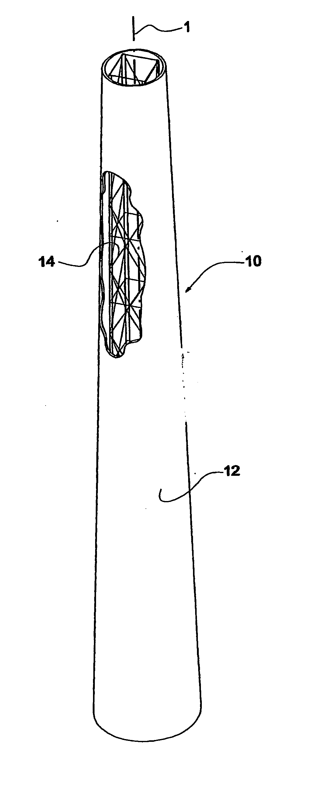
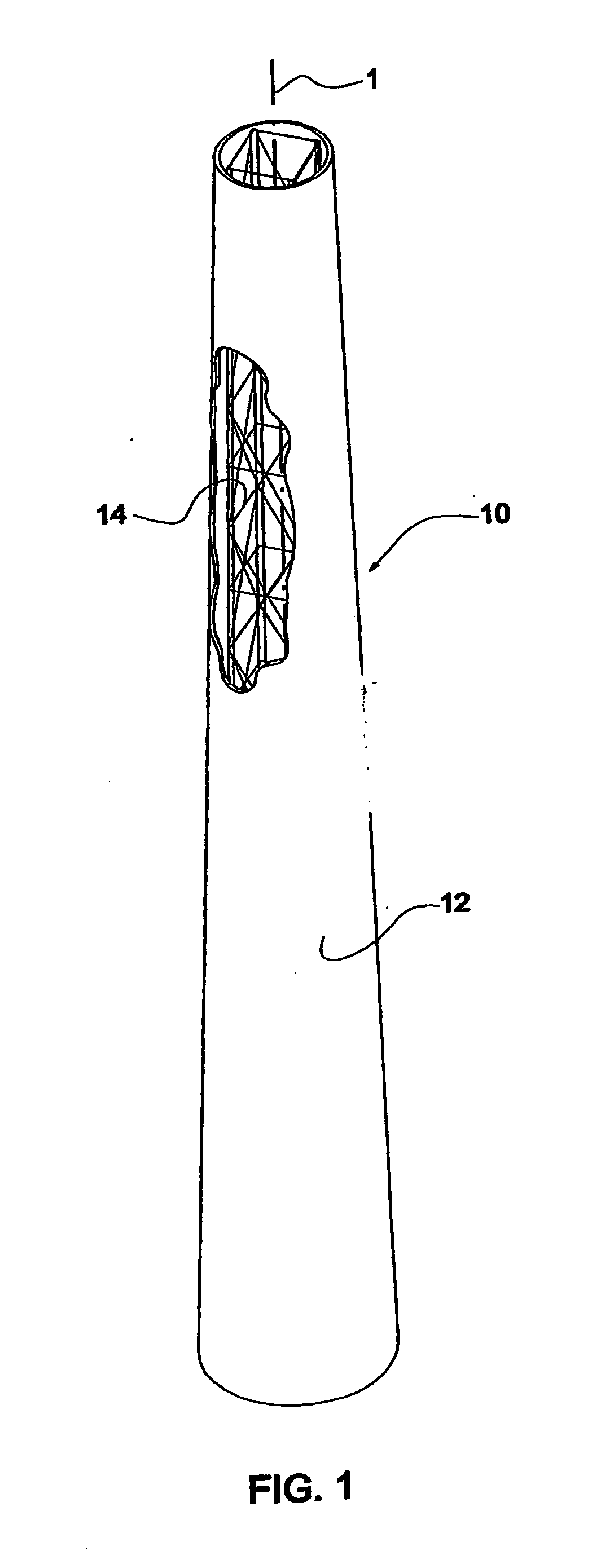
[0051] The objective of the present invention is to provide a solution for a tower that may be substantially tall, would be characterized by the appearance of a monopole, the capacity to support great lateral loads effected upon the objects supported by it by natural forces, such as wind or earthquake, the facility to conceal vertical access ladder and all other installations, such as antenna feeder cables, yet most importantly—be available at an acceptable cost level.

[0052] The heart of the present invention is the basic concept of separation between the structurally functioning elements, which are kept concealed, and a shell which provides the tower its shape, resultantly also governing the lateral wind-drag loads to which the tower will be subjected, yet otherwise said shell has no structural role. The various alternatives for constructing said shell, and the details used therefore, are also important elements of the invention.

[0053] Thus, the present invention facilitates the ...


PUM


Abstract

A solution for a tower (10) that may be substantially tall, characterized by the appearance of a monopole, the capacity to support large objects and consequently sustain great lateral loads generated by wind or earthquake, the facility to conceal vertical access ladder and all other installations, such as antenna feeder cables, and the availability at an acceptable cost level. The heart of the invention is the basic concept of separation between the structurally functioning elements, which are kept concealed, and a non-structural shell (12) which provides the tower (10) the shape of a monopole. The tower (10) comprises, therefore, a tall metal lattice structure (14) having a central vertical axis (1) and certain apparatus for its anchoring to a foundation, concealed within a shell (12) concentric with said central vertical axis (1) and further characterized, at any given level, by a closed cross-section which is either circular or equi-sided polygonal, said shell (12) being internally secured to and supported by said lattice metal structure (14) in an appropriate density throughout its area, so as to maintain its shape when subjected to wind loads or any other likely loads.

Description

FIELD OF THE INVENTION [0001] The present invention relates generally to tall tower structures and, in particular, to towers supporting telecommunication antennae, wind-turbines, large signage or the like. BACKGROUND OF THE INVENTION [0002] The numbers of tall tower structures required globally are consistently increasing in recent years. The major industry sector leading said growth is undoubtedly the telecom sector, but there are several non-telecom applications as well, that require tall towers of possible similar visual and structural properties, such as wind-turbines generating electrical power, large commercial signage of any type or the like. [0003] The vast majority of said towers are made of steel, though other materials, such as concrete or wood, are also used for making towers, yet in much smaller proportions. [0004] A tower made of steel may be constructed as one of two main structural types: as a Lattice Tower, constructed of a plurality of beams and struts, structurall...

Claims


Application Information

Patent Timeline
Patent Type & Authority Applications(United States)
IPC IPC(8): E04H12/10
CPCY02E10/728E04H12/10
Inventor SILBER, MEIR
Owner SILBER MEIR
Why Eureka
Try Eureka