Flare tank apparatus for degassing drilling fluid

Inactive Publication Date: 2005-08-04
WELLCO ENERGY SERVICES PARTNERSHIP
View PDF18 Cites 20 Cited by
  • Summary
  • Abstract
  • Description
  • Claims
  • Application Information

AI Technical Summary

Benefits of technology

[0004] The invention provides a flare tank apparatus for separating combustible gases from a mixture of such gases and a liquid. The apparatus has a degasser for receiving the gases and liquid, with an inlet port, a liquid outlet port and a gas outlet port. A holding tank is operatively connected to the liquid outlet port of the degasser for receiving the liquid that has been separated in the degasser, at least partly, from the gases. The apparatus has a flare stack for conveying the gases from the gas outlet port of the degasser to a burner where they can be burnt off. The apparatus includes an inlet conduit that is opera

Problems solved by technology

The use of a welded connection increases the cost of both conn

Method used


Image

  • Flare tank apparatus for degassing drilling fluid
  • Flare tank apparatus for degassing drilling fluid
  • Flare tank apparatus for degassing drilling fluid

Examples


Example

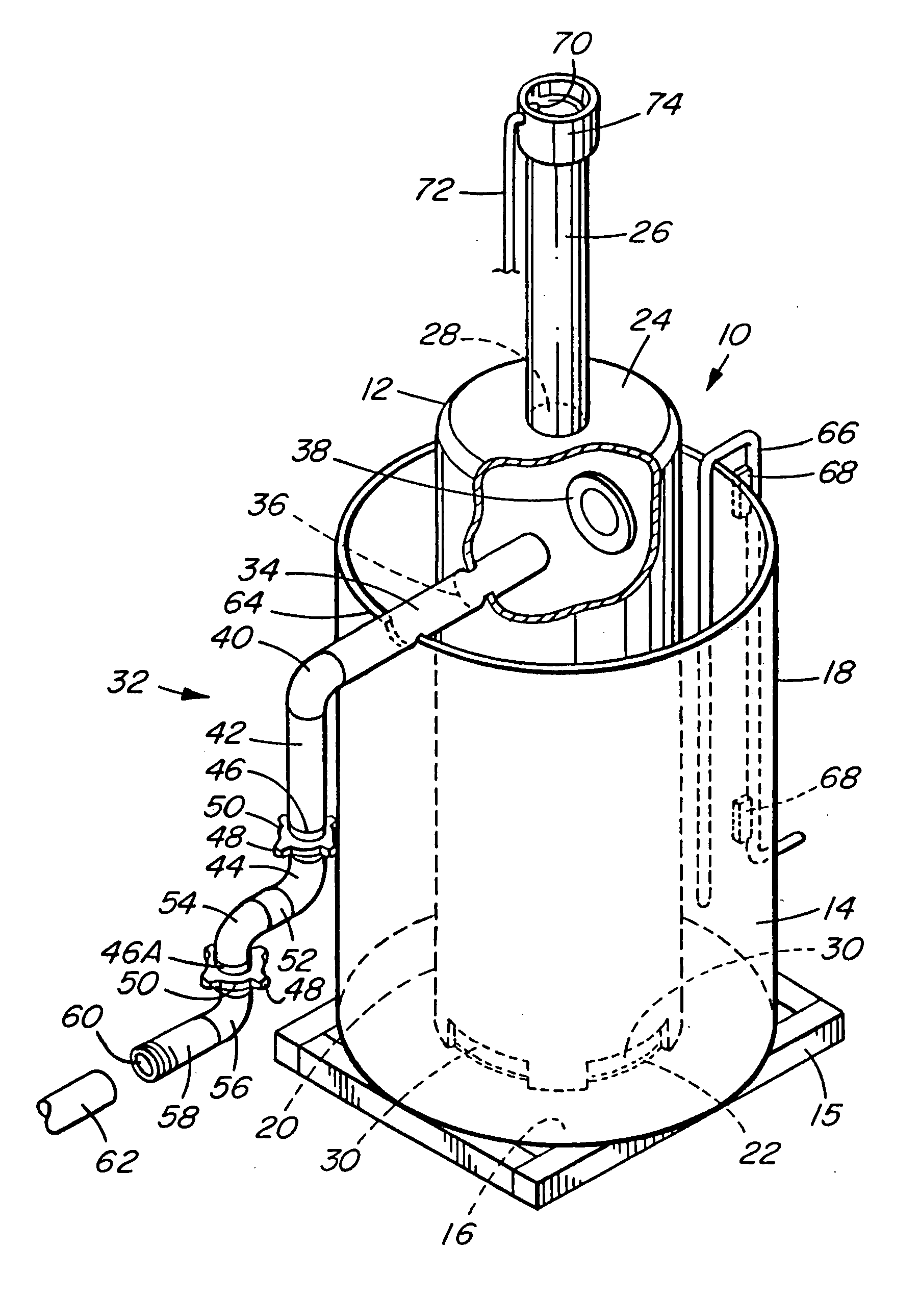
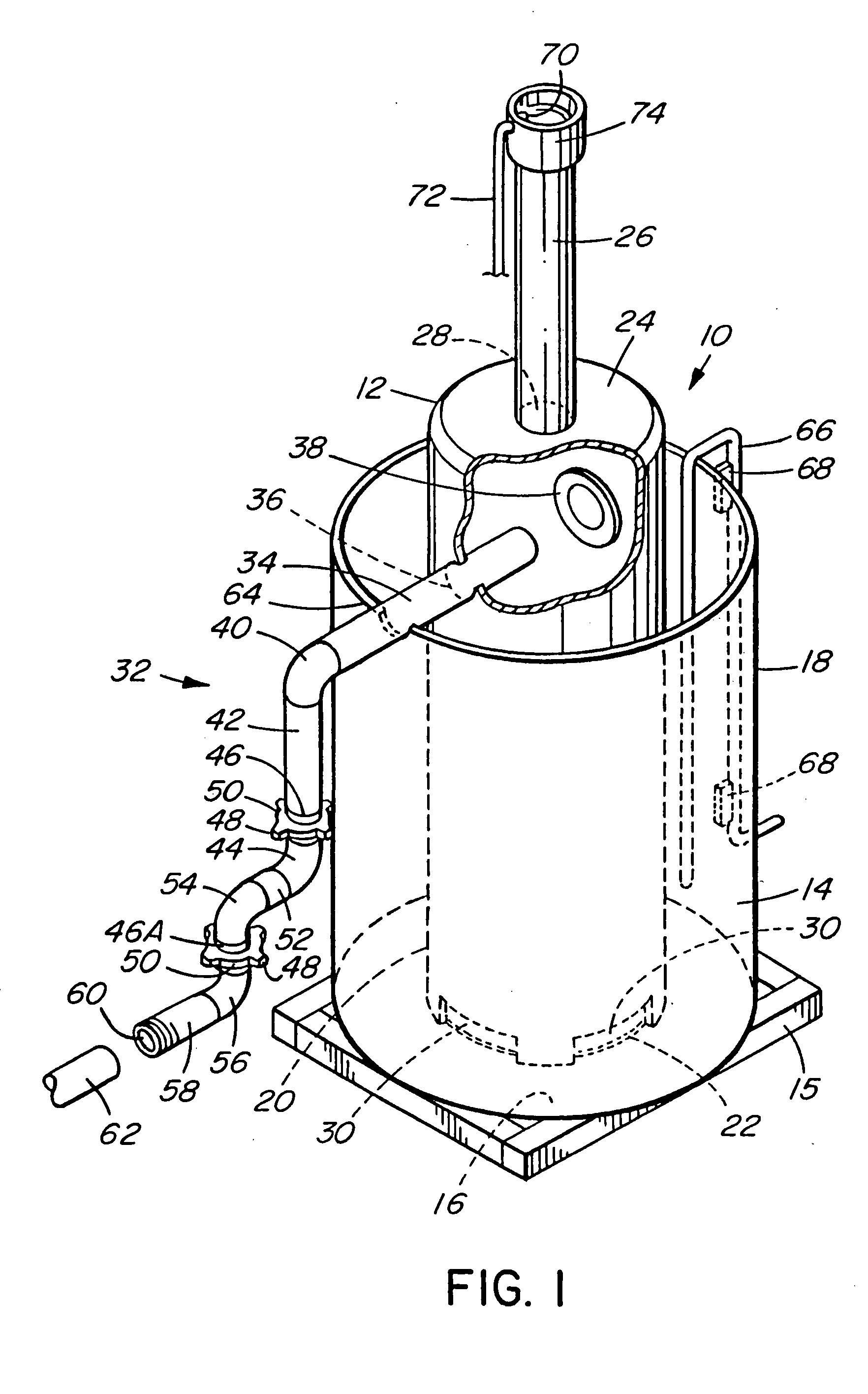
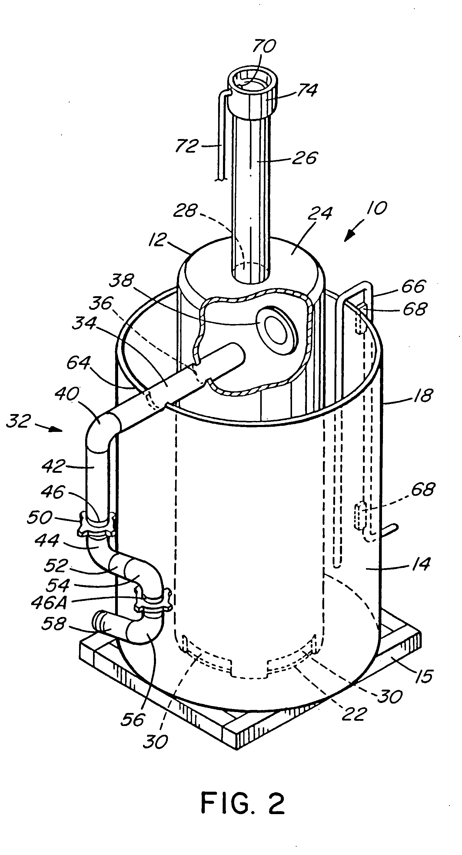
[0012] Flare tank apparatus 10 comprises principally an inner tank or degasser 12 and an outer tank or holding tank 14. The holding tank 14 is an open-top cylindrical tank having a bottom wall 16 and side wall 18. The walls may comprise a double shell for strength and worker safety. The flare tank apparatus is affixed to a skid 15 to facilitate lifting and transport.

[0013] The degasser 12 is a cylindrical tank having a side wall 20, bottom wall 22 and upper wall 24. A flare stack 26 is affixed to the upper wall 24 which has a gas outlet port 28 therein, whereby the interior of the degasser is open to the stack 26. The side wall 20 has liquid outlet ports 30 therein at is lower edge, whereby liquid (principally drilling mud) in the degasser can flow into the holding tank 14, as described below.

[0014] An inlet conduit 32 is adapted to conduct fluid from a flare line 62 into the degasser. It comprises components to facilitate both connection to the flare line and compact placement ag...


PUM

PropertyMeasurementUnit
Angleaaaaaaaaaa
Areaaaaaaaaaaa

Abstract

A flare tank apparatus for separating combustible gases from a mixture of such gases and a liquid, for example combustible gases in drilling fluid from an oil or gas drill string. The apparatus has an inlet conduit having two or more connectors which permit components of the inlet conduit to swivel relative to each other. The connectors can be loosened to permit swivelling without disassembling the inlet conduit. The swivelling of the connectors permits the free end of the inlet conduit to be moved and positioned for connection to the outlet end of a flare line from the drill string and to be positioned against the holding tank of the flare tank apparatus for convenient transport.

Description

TECHNICAL FIELD [0001] The invention pertains to a flare tank apparatus for use in safely separating combustible gases from the fluid produced in oil and gas drilling operations. BACKGROUND [0002] Flare tanks are used in oil and gas drilling operations for disposing of combustible waste gases in a manner that protects oilfield workers. For example, they are commonly used to burn off the small pockets of gas encountered during drilling. They also separate the liquids mixed with the waste gas, such as water and drilling mud, and hold them for disposal by environmentally acceptable means in order to prevent ground contamination. Prior art flare tank apparatuses are described, for example, in U.S. Pat. Nos. 5,807,095, 5,882,187 and 5,997,284 (Gustafson et al.). [0003] Flare tanks may be portable apparatuses that are moved to job sites as needed. At a job site, the flare tank is connected to a flare line, i.e. the conduit that extends from the drill string and carries to the flare tank t...

Claims


Application Information

Patent Timeline
IPC IPC(8): B01D19/00
CPCB01D19/0042
Inventor ROSS, STANLEY R.J.ROSS, RODDY J.
Owner WELLCO ENERGY SERVICES PARTNERSHIP
Why Eureka
Try Eureka