Automated cage cleaning apparatus and method

a cage cleaning and automatic technology, applied in the direction of cleaning process and apparatus, chemistry apparatus and processes, cleaning using liquids, etc., can solve the problems of complicated automatic removal of cage bottoms from conveyers, skewed cage bottoms on conveyers, and the need for frequent cleaning of cages, etc., to achieve more versatility in design

Inactive Publication Date: 2005-08-04
MATRIX SCI
View PDF11 Cites 70 Cited by
  • Summary
  • Abstract
  • Description
  • Claims
  • Application Information

AI Technical Summary

Benefits of technology

[0015] The soiled and clean side robots of the present invention further comprise bases that are slidably mounted on a rail. This configuration provides the robots with an additional axis of movement, allowing more versatility in designing cage cleaning facilities. The robots also comprise a vertical rail, substantially perpendicular to the base, and an arm segment extending outward, substantially perpendicular to said vertical rail. Attached to a distal end of the arm segment is a gripping means. The gripping means and arm segment are adapted to firmly grasp a plurality of cage bottoms, invert the cage bottoms, and move the cage bottoms to the next stage in the process.

Problems solved by technology

While in use the bedding becomes soiled, thereby necessitating the need for frequent cleaning of the cages.
Due to the extreme force of the streaming water required to clean the cage bottoms, the high velocity air required for drying, and the transfer of components between conveyers, the cage bottoms become skewed on the conveyer.
The unpredictable arrangement of the skewed cage bottoms complicates automated removal of the cage bottoms from the conveyer.
Because of the turbulent conditions of the process described above, the robotic arm can not efficiently remove the cage bottoms from the conveyer.
Because the base of the robotic arm is fixedly mounted to the ground, the area serviced by the robotic arm is limited to the area about the base.
Furthermore, this configuration strictly limits the positioning of equipment accessed by the robotic arm, and thereby limits options in designing cage cleaning facilities.

Method used


Image

  • Automated cage cleaning apparatus and method
  • Automated cage cleaning apparatus and method
  • Automated cage cleaning apparatus and method

Examples


Embodiment Construction

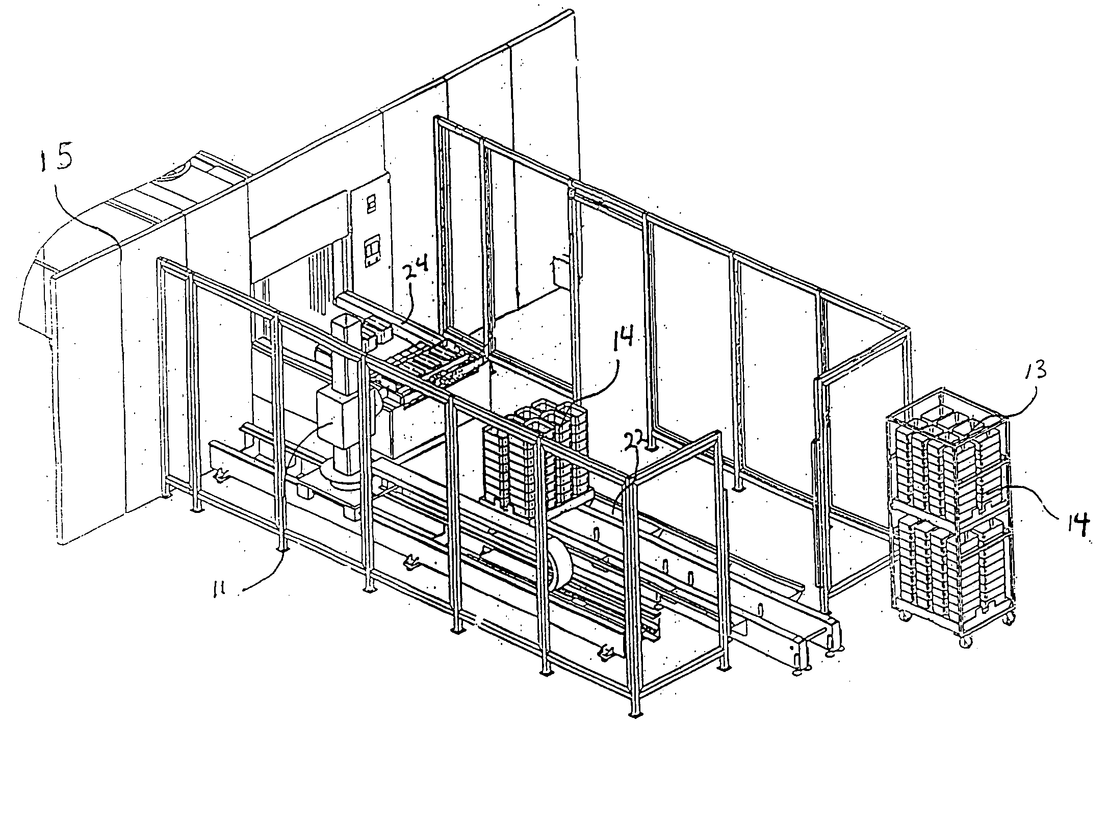
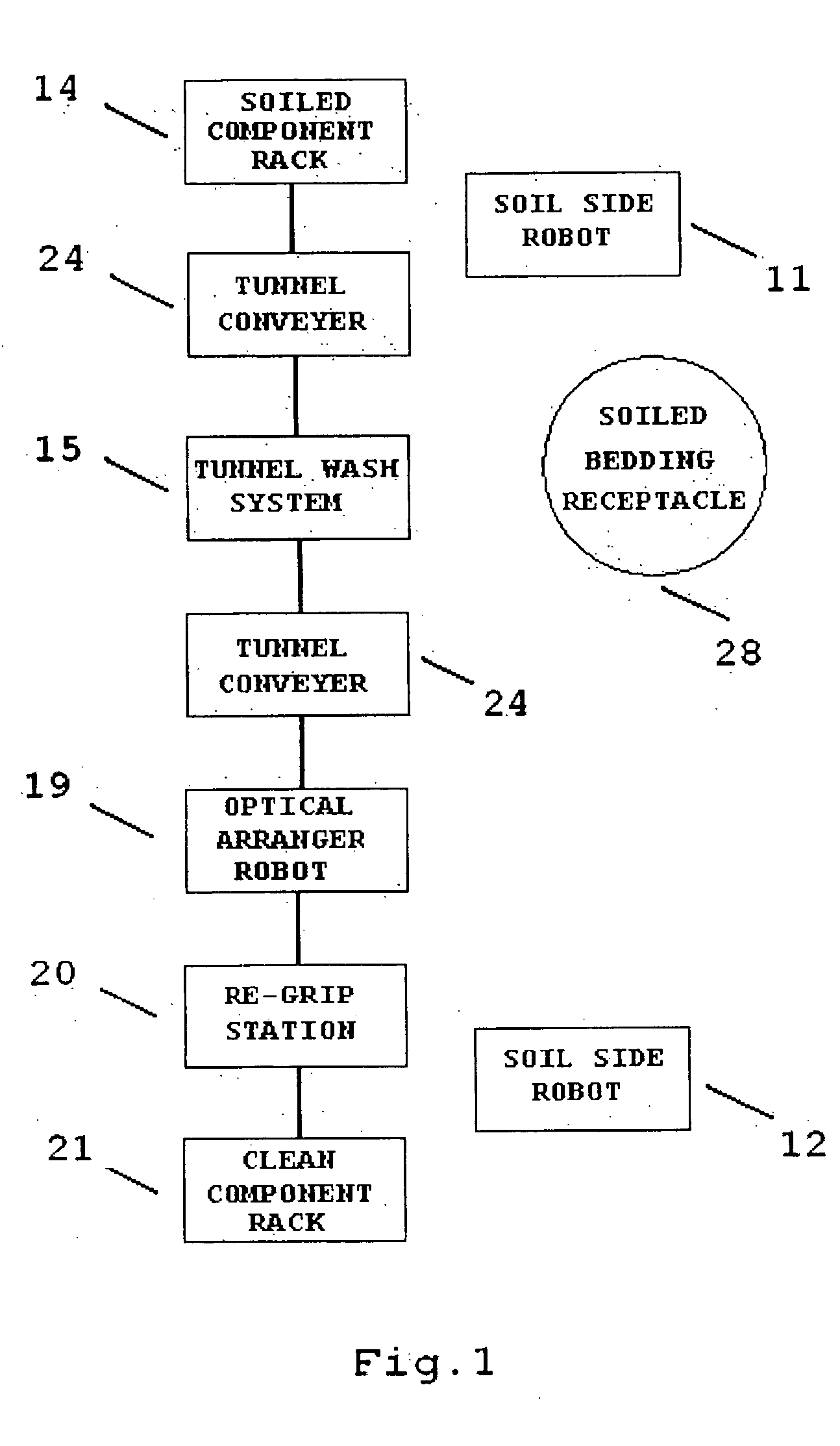
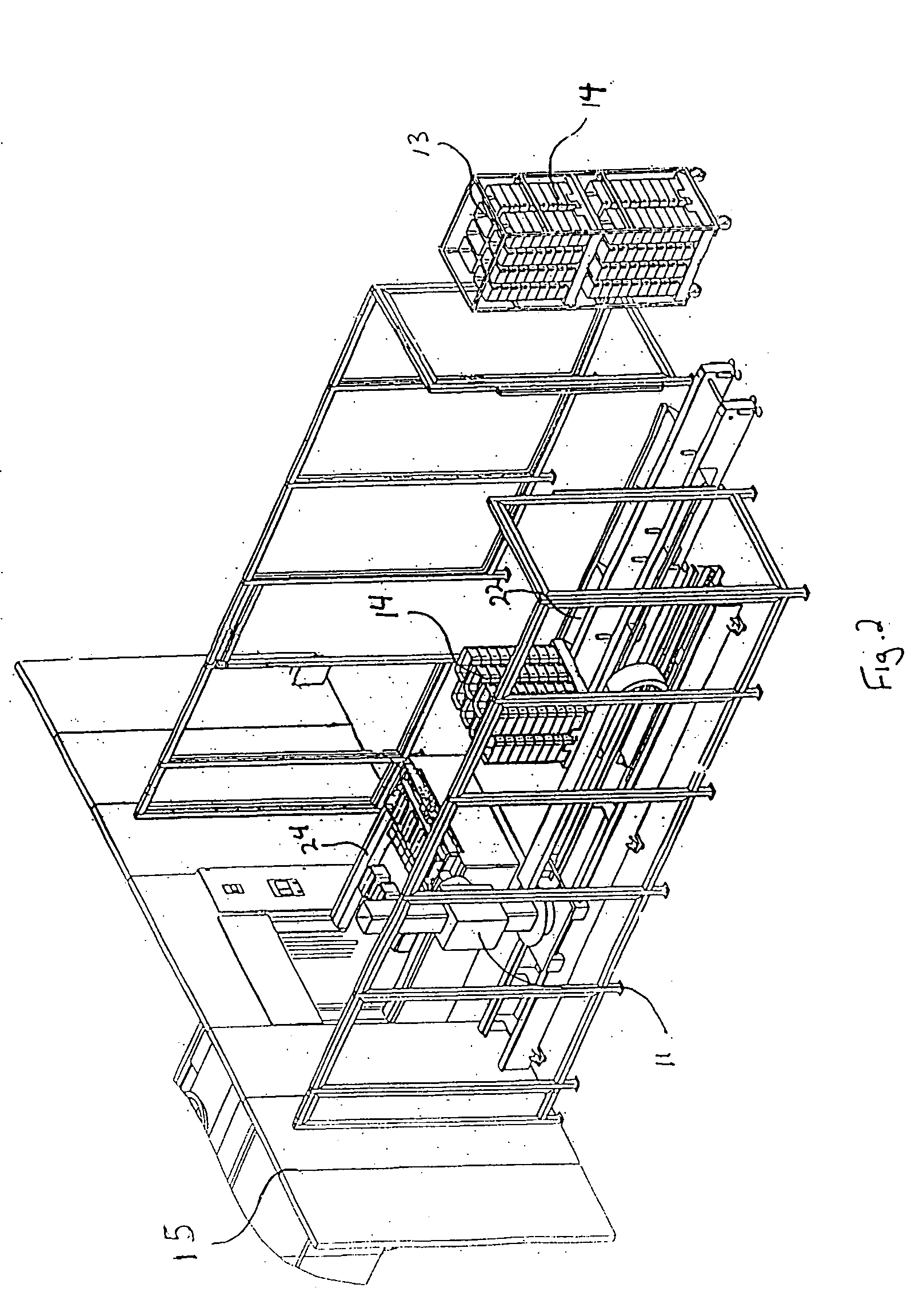
[0021] Referring to FIGS. 1-3, a flow diagram and perspective views of the improved apparatus and method for cleaning animal cages are shown. The apparatus includes a pair of loading / unloading robots, referred to hereinafter as the soil side robot 11, and the clean side robot 12. Additionally, the apparatus further comprises optical arranger robot 19. In operation, the soiled cage components arrive at the cleaning area on a component cart 13, or any suitable device for transporting a plurality of soiled components. The cart further comprises at least one soiled component rack 14 holding soiled cage bottoms, wherein the rack of soiled cage bottoms is attachable to an in-feed conveyer 22. Once the rack 14 is securely attached upon the in-feed conveyer 22, it advances toward soil side robot 11. The soil side robot 11 grasps a plurality of cage bottoms from the rack 14, inverts the cage bottoms over a soiled bedding receptacle 28 (FIG. 1), or any device suitable for receiving the soiled...


PUM


Abstract

The automated cage cleaning system is comprised of a pair of robotic arms, a soil side robot and a clean side robot. The soil side robot is utilized for removing the dirty cage bottoms from a cart, rack, pallet, or fixture, emptying soiled bedding from the cage bottoms, and placing the cage bottoms on a conveyer leading to the tunnel washing equipment. The clean side robot is used to grip the clean cage bottoms, and place the cage bottoms on a cart, rack, pallet, or fixture. Additionally, the present invention comprises an optical arranger robot with vision processing for detecting, and moving skewed cage bottoms to a re-grip station. From the re-grip station, the clean side robot places the cage bottoms on a rack, pallet, fixture, or any other device suitable for holding a plurality of cage bottoms.

Description

TECHNICAL FIELD [0001] The present invention relates to an improved apparatus and method for cleaning the cages of laboratory animals. BACKGROUND OF THE INVENTION [0002] A conventional cage system for holding small laboratory animals is typically a three piece assembly having a clear plastic bottom, a grill for holding food and water, and a lid that attaches to the bottom and holds the grill in place. Additionally, a suitable bedding material, such as cedar shavings, is added to the bottom portion of the cage assembly to absorb animal waste and spilled food. [0003] While in use the bedding becomes soiled, thereby necessitating the need for frequent cleaning of the cages. The cleaning process requires disassembly of the cage, removal of the soiled bedding from the bottom portion, washing, and drying the cage elements. Furthermore, upon completion of the aforementioned steps, clean bedding is added to the cage. [0004] Robotic arms are known to assist laboratory personnel with this pro...

Claims


Application Information

Patent Timeline
Patent Type & Authority Applications(United States)
IPC IPC(8): A01K1/01A01K1/03B08B3/02
CPCB08B3/022A01K1/031
Inventor AUSTIN, DARYLHORETH, EDWARD J.DINEL, DARRYLPOTTER, RONALD
Owner MATRIX SCI
Why Eureka
Try Eureka