Pneumatic tire for ice-bound or snow-covered road

a pneumatic tire and snow-covered technology, applied in the field of pneumatic tires, can solve the problems of tire not fully exerting its inherent drive performance, snow clogging, snow clogging, etc., and achieve the effect of improving the ability to eliminate snow on the tread surface, early exertion of properties, and improving brake and drive performan

Inactive Publication Date: 2005-08-04
YOKOHAMA RUBBER CO LTD
View PDF2 Cites 30 Cited by
  • Summary
  • Abstract
  • Description
  • Claims
  • Application Information

AI Technical Summary

Benefits of technology

[0013] As described above, a plurality of fine grooves shallower than the sipes are formed in the tread surface of the land, and the angle of the fine groove with the circumferential direction of the tire lies between 42 and 60 degrees inclusive. This configuration allows achieving an adequate effect of the edges of the fine grooves during braking or driving, without impairing the effect of removing a water film developing between an ice-bound road surface and the tread surface and the capability of eliminating snow on the tread surface. Therefore, this enables significant improvement in the brake and drive performance on ice-bound roads in early periods of wear. Moreover, the fine grooves wear away early by frictional force, which is rec

Problems solved by technology

However, since a tire before a break-in does not sufficiently have the aforementioned asperities on a tread surface thereof, the tire has had a disadvantage in that the tire cannot fully exert its inherent drive performance in early periods of wear.
However, the tire may have inadequate drainage of snow in the fine grooves, which may cause snow clogging.
Similarly, the tire according to the latter approach above, having the auxiliary sipings formed on the tread surface, may have inadequate drainage of snow in the auxiliary sipings, which may cause snow clogging.
Thus, these tires have a problem as given below.
The occurrence of snow clogging mentioned above leads to a reduction in the amount of snow taken in, thus to a reduction in the contact area, and thus to degradation in brake and drive performance on ice-bound roads, when the fine grooves or the auxiliary sipings come into another contact with

Method used


Image

  • Pneumatic tire for ice-bound or snow-covered road
  • Pneumatic tire for ice-bound or snow-covered road
  • Pneumatic tire for ice-bound or snow-covered road

Examples


Embodiment Construction

[0027] The invention will be described in detail below with reference to the accompanying drawings.

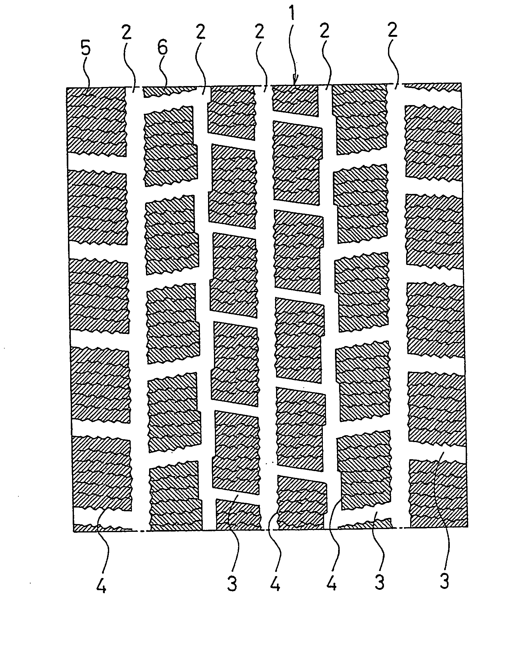
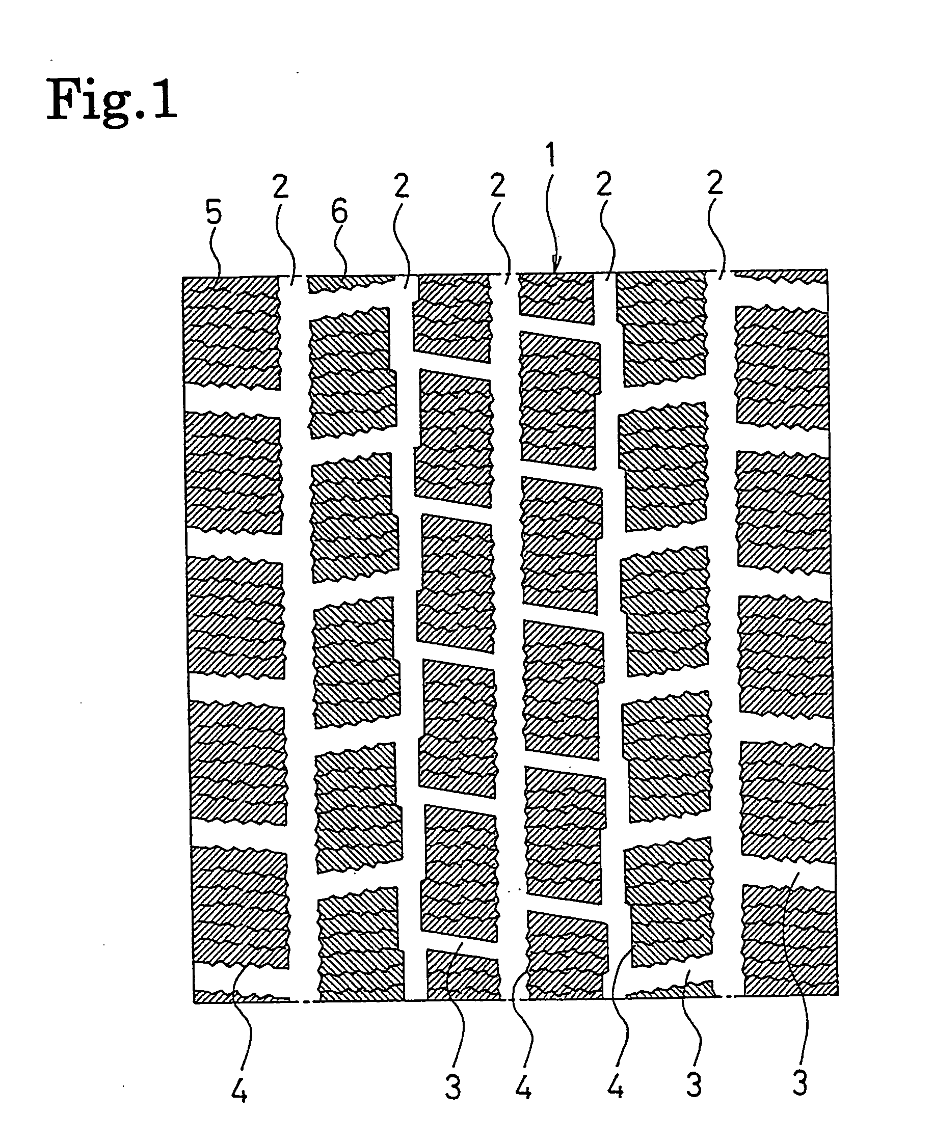
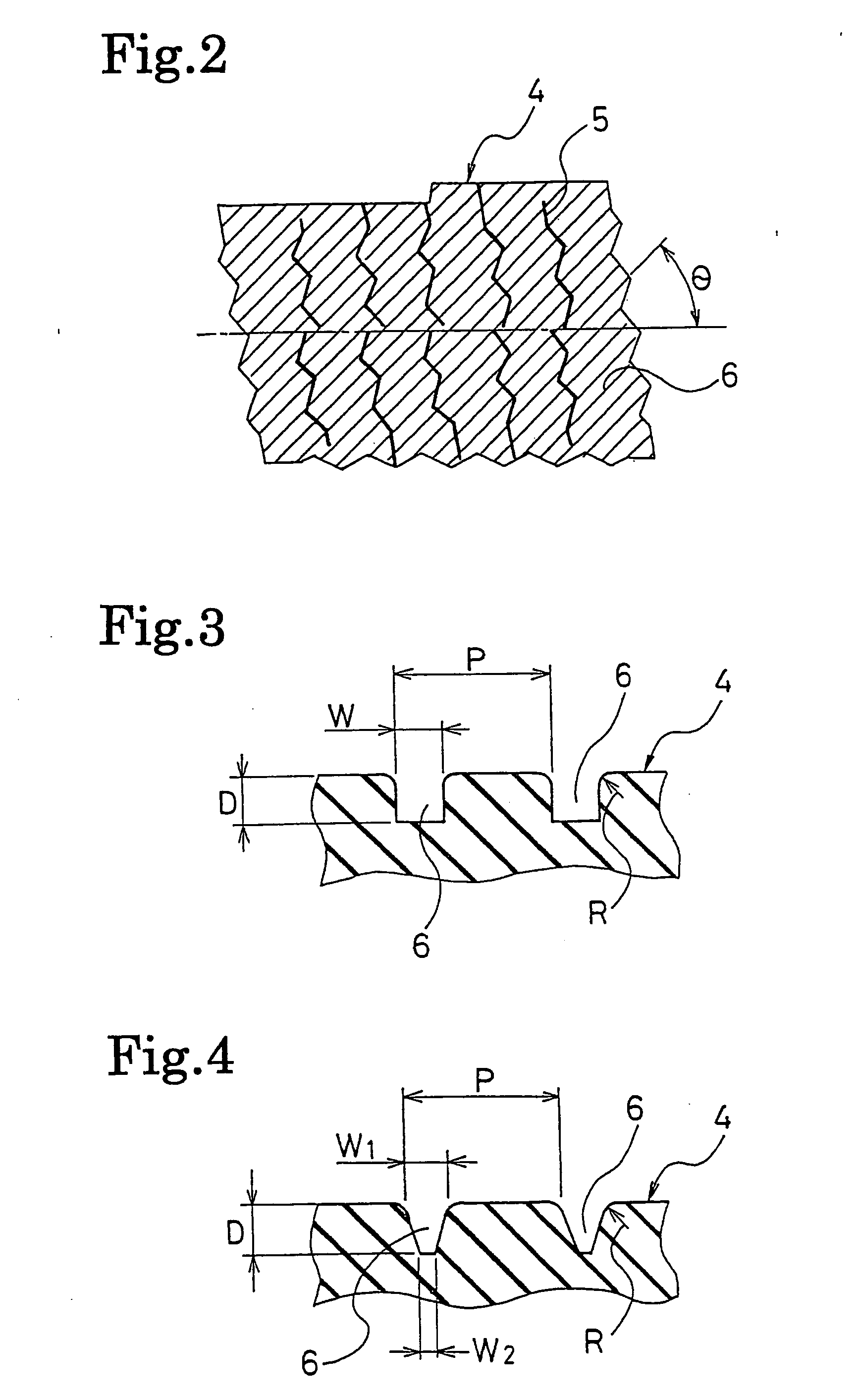
[0028]FIG. 1 shows a tread pattern of a pneumatic tire for ice-bound or snow-covered roads according to an embodiment of the invention. FIG. 2 illustrates an enlarged view of a block in the tread pattern shown in FIG. 1. FIG. 3 illustrates an enlarged view of fine grooves formed in the block shown in FIG. 2.

[0029] As shown in FIG. 1, tread 1 is provided with a plurality of main grooves 2 extending in a circumferential direction of a tire, and a plurality of lateral grooves 3 extending in a width direction of the tire. The tread 1 is partitioned into a plurality of lands, which are formed of a plurality of blocks 4, by the main grooves 2 and the lateral grooves 3. Each block 4 has a plurality of sipes 5 formed therein. The composition of rubber constituting the tread 1 has a filler or foam mixed therein so that microscopic asperities having the effect of removing a water film develop ...


PUM


Abstract

A pneumatic tire for ice-bound or snow-covered roads, which has fine grooves formed in a tread surface, thereby improving brake and drive performance on ice-bound roads in early periods of wear. This pneumatic tire for ice-bound or snow-covered roads has its tread partitioned into a plurality of lands, these lands being formed with sipes, wherein the tread surface at the lands is formed with a plurality of fine grooves shallower than the sipes, the edges of these fine grooves being curved. Further, the width of the openings of the fine grooves is larger than the width of the bottoms thereof. Further, the angle of the fine grooves with the circumferential direction of the tire is 42 to 60 degrees.

Description

FIELD OF THE INVENTION [0001] The invention relates to a pneumatic tire suitable for ice-bound or snow-covered roads, and more particularly to a pneumatic tire for ice-bound or snow-covered roads, which has fine grooves formed in a tread surface, thereby improving brake and drive performance on ice-bound roads in early periods of wear. DESCRIPTION OF THE RELATED ART [0002] For example, pneumatic tires for ice-bound or snow-covered roads, typified by studless tires, have a filler or foam mixed in tread rubber so that microscopic asperities develop on a tread surface. The asperities exert the effect of removing a water film on ice-bound roads, and thus contribute to improvement in drive performance on such roads. However, since a tire before a break-in does not sufficiently have the aforementioned asperities on a tread surface thereof, the tire has had a disadvantage in that the tire cannot fully exert its inherent drive performance in early periods of wear. [0003] As one technique fo...

Claims


Application Information

Patent Timeline
IPC IPC(8): B60C11/12B60C11/13
CPCB60C11/12Y10S152/03Y10S152/902B60C2011/1245B60C2011/1277B60C2011/1231B60C2011/1213
Inventor HASHIMOTO, YOSHIMASA
Owner YOKOHAMA RUBBER CO LTD
Why Eureka
Try Eureka