Detector for x-ray computer tomography scanners

Inactive Publication Date: 2005-08-04
SIEMENS HEALTHCARE GMBH
View PDF9 Cites 7 Cited by
  • Summary
  • Abstract
  • Description
  • Claims
  • Application Information

AI Technical Summary

Benefits of technology

[0005] An object of an embodiment of the invention is to reduce or even eliminate at least one of the disadvantages according to the prior art. In particular, one aim, in one embodiment, is to disclose an x-ray computer tomography scanner including a detector that is as simple as possible and inexpensive to produce, with which an increased resolution is possible in the z direction where there is a set number or height of lines.
[0006] According to an embodiment of the invention, a device that partially covers the surface of the scintillator elements is provided, which partially covers the surface of the scintillator elements, for reducing the size of the aperture in the z direction. The step that is suggested allows an increase in the resolution in the z direction, in a simple and inexpensive manner. The proposed solution is universal. Conventional scintillator elements can be used. Retroactive conversion of conventional multi-line detectors is also possible.
[0007] Usefully, the device for reducing the size of the aperture is formed from a plurality of parallel adjacent strips, the strips advantageously covering the edges of the scintillator elements that run in the x direction. The proposed features also make it possible to use scintillator elements, the edges whereof hav

Problems solved by technology

For technical reasons, the height of the scintillator elements cannot be reduced at will.
For

Method used


Image

  • Detector for x-ray computer tomography scanners
  • Detector for x-ray computer tomography scanners
  • Detector for x-ray computer tomography scanners

Examples


Example

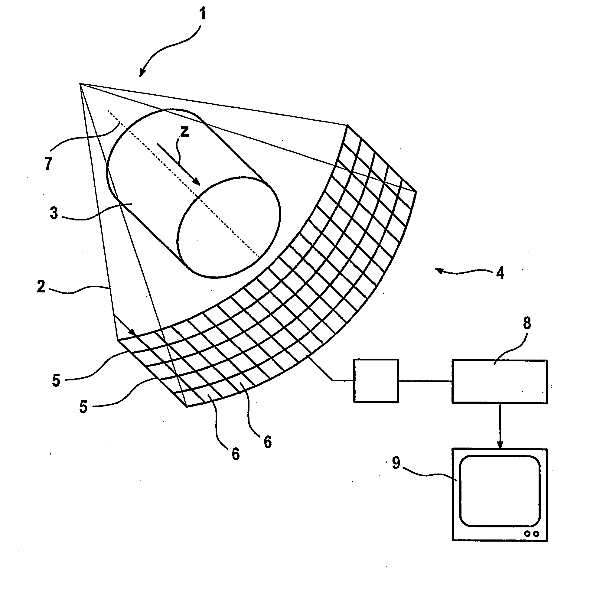
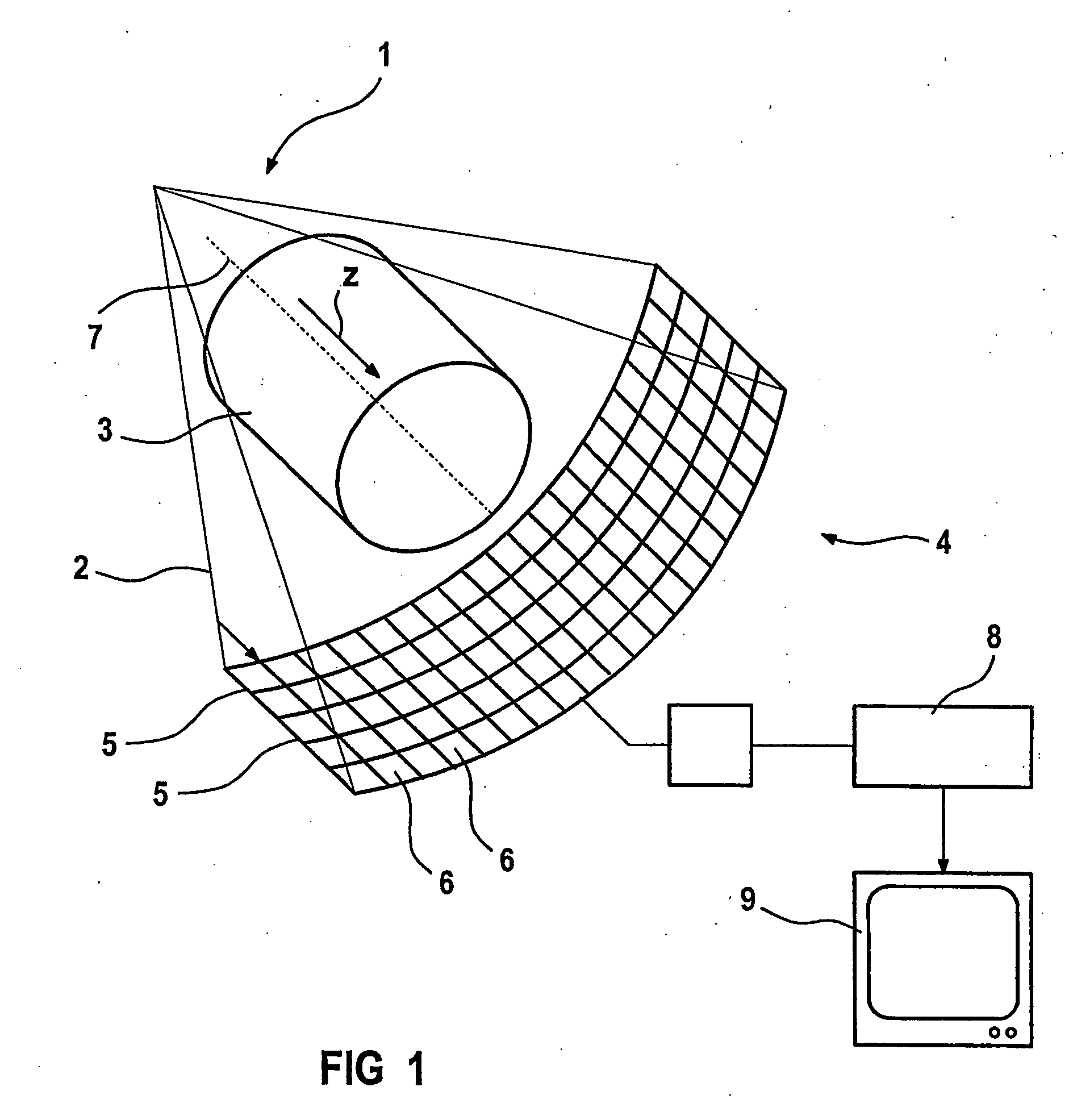
[0016]FIG. 1 shows a focal point 1 of an x-ray beam emitter from which comes a fan-shaped beam of x-rays blended together by a surround that is not shown, which beam penetrates an object 3 and impinges on a detector 4. The detector 4 has a plurality of parallel detector lines 5, each of which is formed from a plurality of adjacent scintillator elements 6. A z axis that runs parallel to the axis of the irradiated object 3 is marked with the reference character 7. The z axis is parallel to the axis of rotation of a measuring system that includes the detector 4.

[0017] The measuring system rotates around the axis of rotation 7 such that the object 3 is x-rayed at various angles of projection. From the detector signals produced during the above process, a computer 8 calculates an image of the object 3 which is reproduced on a monitor 9.

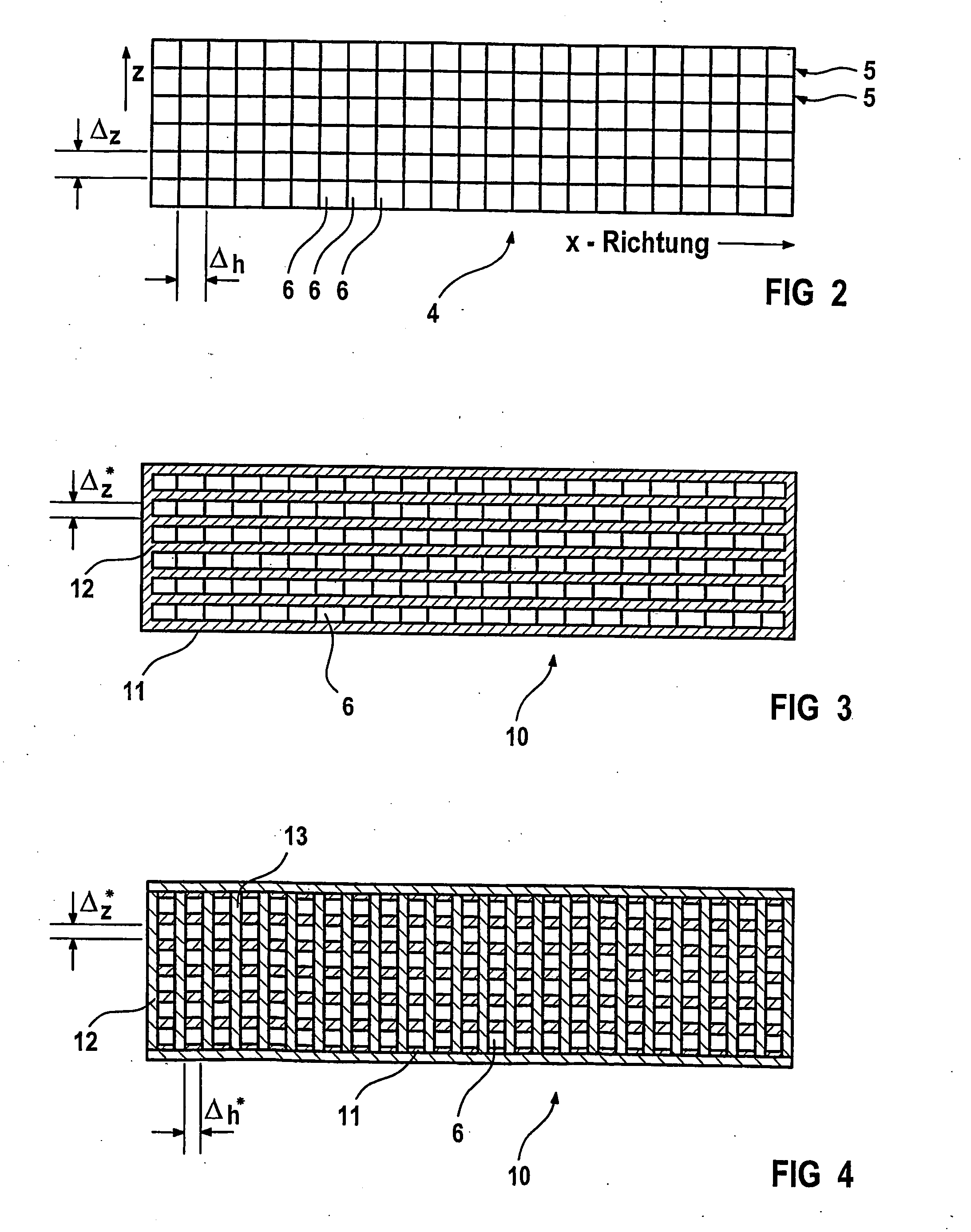
[0018]FIG. 2 shows a top view of the detector 4. The detector includes a plurality of adjacent detector lines 5 in the z direction. Each line consists o...


PUM


Abstract

A detector for x-ray computer tomography scanners, includes a number of adjacent detector lines extending in an x direction, whereby each detector line is formed from a multitude of adjacent scintillator elements. In order to increase the resolution in the z direction and to simplify the design of the detector, the surface of the scintillator elements are partially covered, which further serves to reduce the size of the aperture in the z direction.

Description

[0001] This application is the national phase under 35 U.S.C. § 371 of PCT International Application No. PCT / DE03 / 00739 which has an International filing date of Mar. 7, 2003, which designated the United States of America and which claims priority on German Patent Application number DE 102 11 948.1 filed Mar. 18, 2002, the entire contents of which are hereby incorporated herein by reference.FIELD OF THE INVENTION [0002] The invention generally relates to an x-ray computer tomography scanner comprising a detector. BACKGROUND OF THE INVENTION [0003] A computer tomography scanner that includes a detector is known, for example, from DE 195 02 574 A1. The detector of the known x-ray computer tomography scanner is a so-called multi-line detector. It includes a plurality of detector lines that are arranged in the direction of the axis of an object that is to be irradiated, for example, a patient. The aforementioned axis is also referred to as the z axis. In an x direction running perpendic...

Claims


Application Information

Patent Timeline
IPC IPC(8): G01N23/04G01T1/164G01T1/20G01T7/00G21K1/02
CPCG01T1/1642G21K1/025G01T1/2018G01T1/2006
Inventor BRUDER, HERBERTFLOHR, THOMASSTIERSTORFER, KARL
Owner SIEMENS HEALTHCARE GMBH
Why Eureka
Try Eureka