Method for controlling striations in a lamp powered by an electronic ballast

a technology of electronic ballast and control method, which is applied in the direction of process control, lighting and heating apparatus, instruments, etc., can solve the problems of increasing the cost and loss associated with electronic ballast, and suffering from the same disadvantag

Inactive Publication Date: 2005-08-04
UNIVERSAL LIGHTING TECHNOLOGIES
View PDF18 Cites 9 Cited by
  • Summary
  • Abstract
  • Description
  • Claims
  • Application Information

AI Technical Summary

Benefits of technology

[0011] One of the objects of the present invention is to provide a method of controlling striations in a lamp powered by an electronic ballast that does not require the use of additional components specifically included in the ballast for that purpose. Or, to put it

Problems solved by technology

The primary disadvantage of these methods is that they require electronic ballasts that include additional components for generating the DC or low frequency AC currents and these additional components increase the costs and losses associated with the electronic ballasts.
This method suffers from the same disadvantage as the method taught by the '763 patent.
T

Method used


Image

  • Method for controlling striations in a lamp powered by an electronic ballast
  • Method for controlling striations in a lamp powered by an electronic ballast
  • Method for controlling striations in a lamp powered by an electronic ballast

Examples


Embodiment Construction

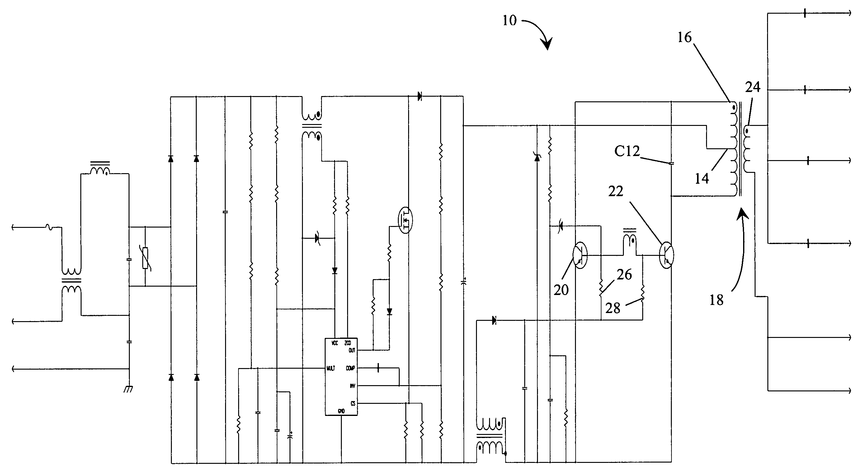
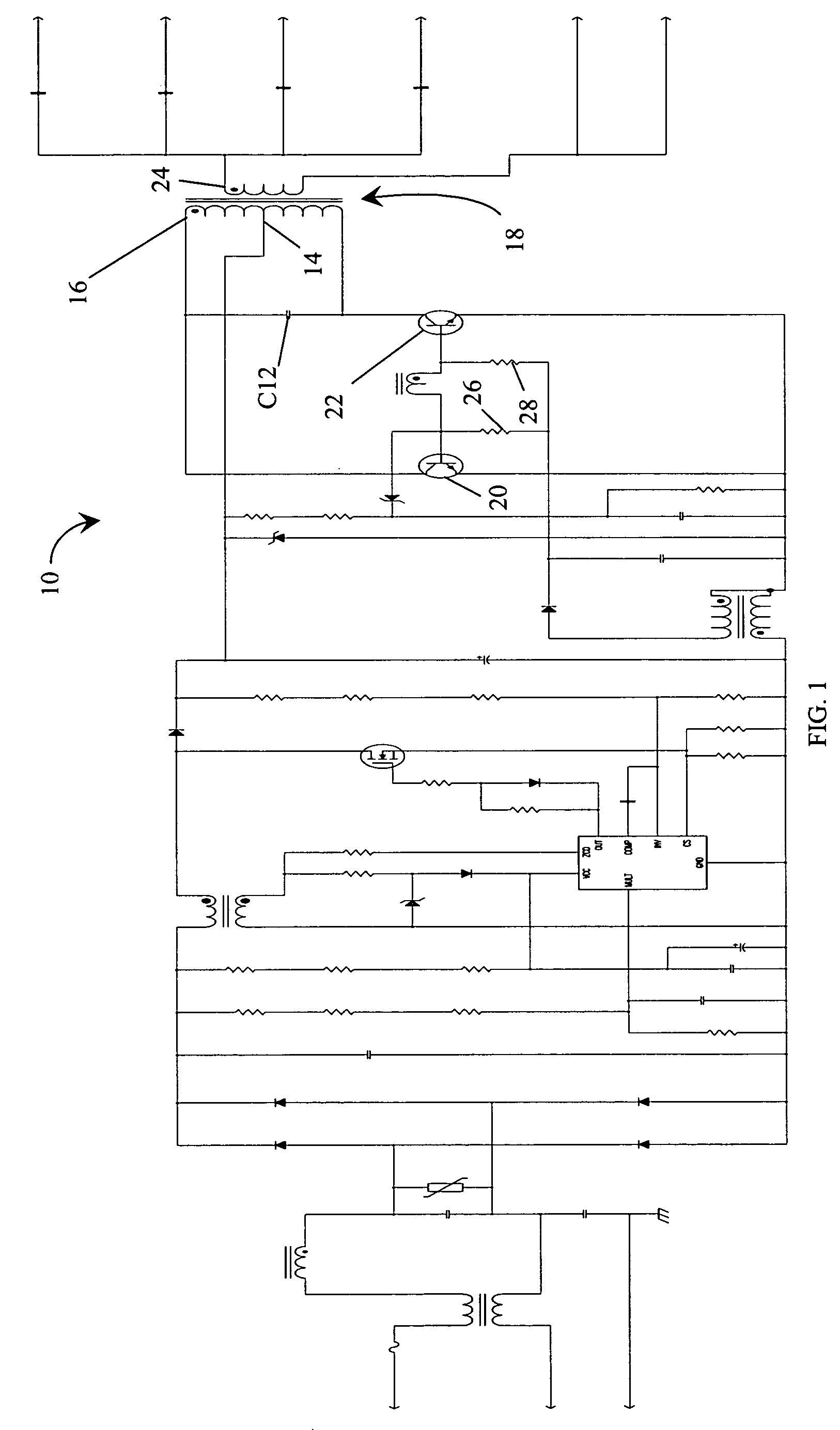
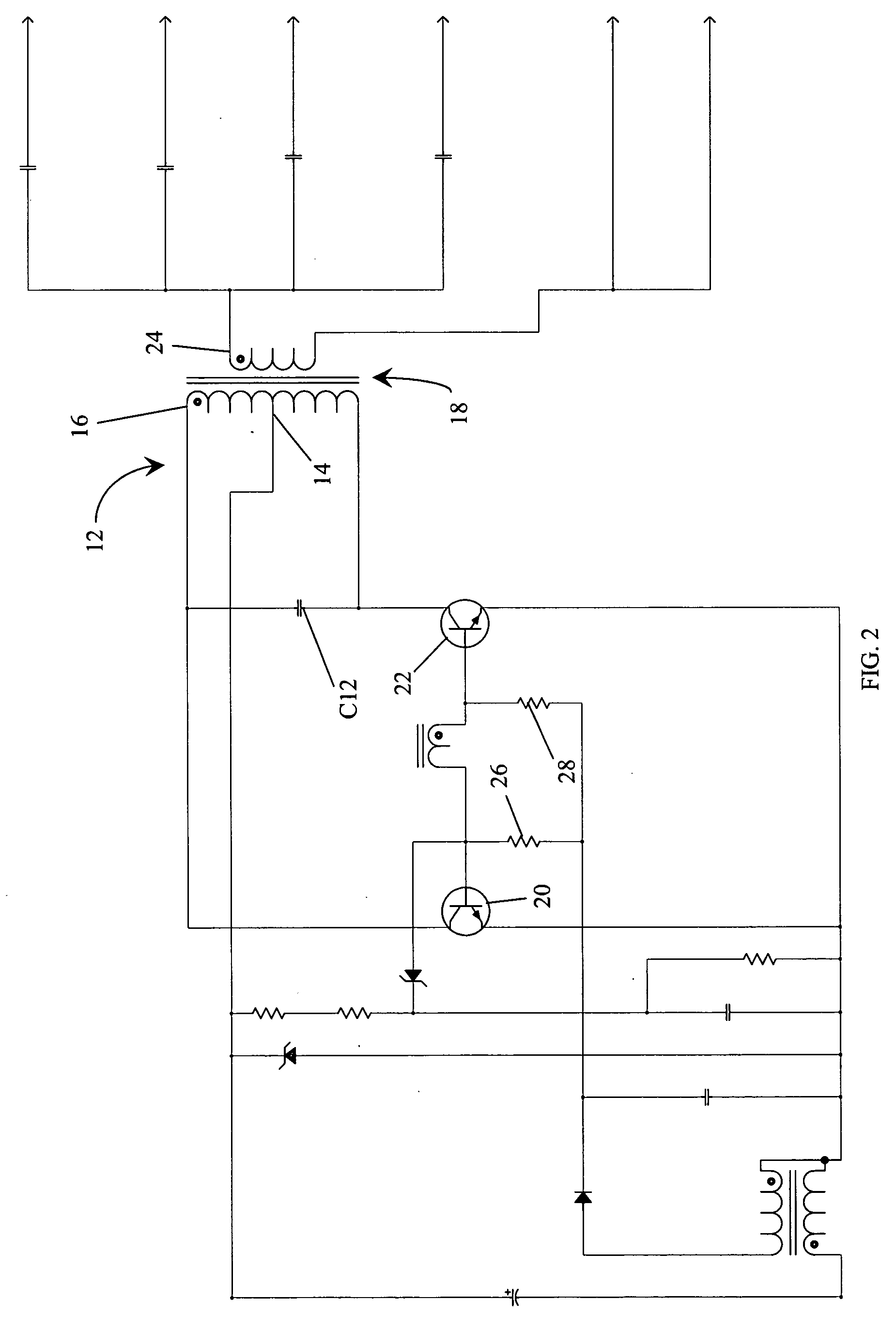
[0026] In the following discussion, the present invention is discussed with reference to what is commonly referred to as a current-fed, parallel resonant push pull ballast and a current-fed, parallel resonant half bridge ballast. It should be noted that the various aspects of the present invention are not limited to these particular types of ballasts and may be applied to other ballasts as well.

[0027]FIGS. 1-2 are schematic drawings of a conventional parallel resonant push pull electronic ballast circuit 10. FIG. 1 is a drawing of the entire ballast 10 and FIG. 2 is an enlarged view of a portion of the ballast 10 including a push pull inverter circuit 12. The operation of this type of ballast is well known in the art and will not be discussed in detail. In general, however, the ballast 10 is operable to receive a low frequency, 60 Hz, voltage input, convert that input into a substantially constant DC voltage, and then convert that DC voltage into a high frequency (typically greater...


PUM


Abstract

A method for controlling striations in a lamp powered by an electronic ballast includes the steps of generating an asymmetric lamp current using an unbalanced circuit component in the electronic ballast and supplying that current to the lamp. The unbalanced circuit component may be an unbalanced output transformer or an unbalanced DC choke. The output transformer is unbalanced by offsetting the number of turns on each side of the tap on the primary winding of the transformer. In a similar manner, the DC choke is unbalanced by offsetting the number of turns in each winding of the choke.

Description

[0001] This application is a Non-Provisional Utility application which claims benefit of co-pending U.S. Patent Application Ser. No. 60 / 540,187 filed Jan. 29, 2004, entitled “Methods of Striation Control for Current Fed, Parallel Resonant Inverters” which is hereby incorporated by reference. [0002] A portion of the disclosure of this patent document contains material that is subject to copyright protection. The copyright owner has no objection to the facsimile reproduction by anyone of the patent document or the patent disclosure, as it appears in the Patent and Trademark office patent file or records, but otherwise reserves all copyright rights whatsoever. [0003] Be it known that I, Thomas M. Poehlman, a citizen of the United States, residing in Madison, Ala. 35758, have invented a new and useful “Method For Controlling Striations In A Lamp Powered By An Electronic Ballast.”BACKGROUND OF THE INVENTION [0004] The present invention relates generally to controlling striations in lamps...

Claims


Application Information

Patent Timeline
IPC IPC(8): F21V19/02H05B41/14H05B41/285H05B41/36
CPCH05B41/2858
Inventor POEHLMAN, THOMAS M.
Owner UNIVERSAL LIGHTING TECHNOLOGIES
Why Eureka
Try Eureka