Adjusting circuit and method
a technology of adjustment circuit and image display device, which is applied in the direction of color signal processing circuit, color television details, instruments, etc., can solve problems such as color other than white color going wrong, and achieve the effect of fine color adjustmen
- Summary
- Abstract
- Description
- Claims
- Application Information
AI Technical Summary
Benefits of technology
Problems solved by technology
Method used
Image
Examples
first embodiment
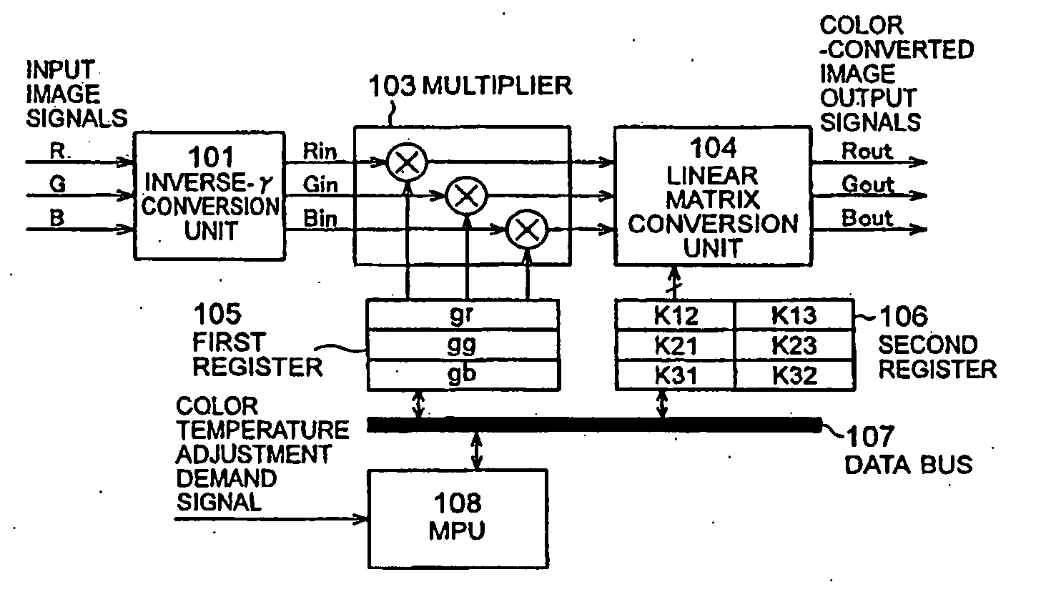
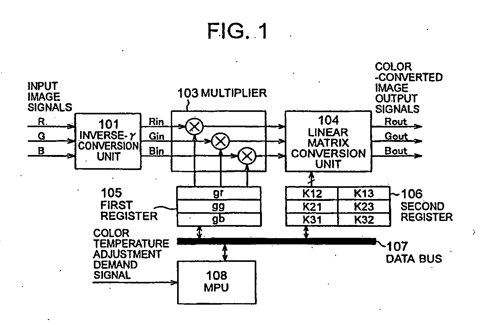
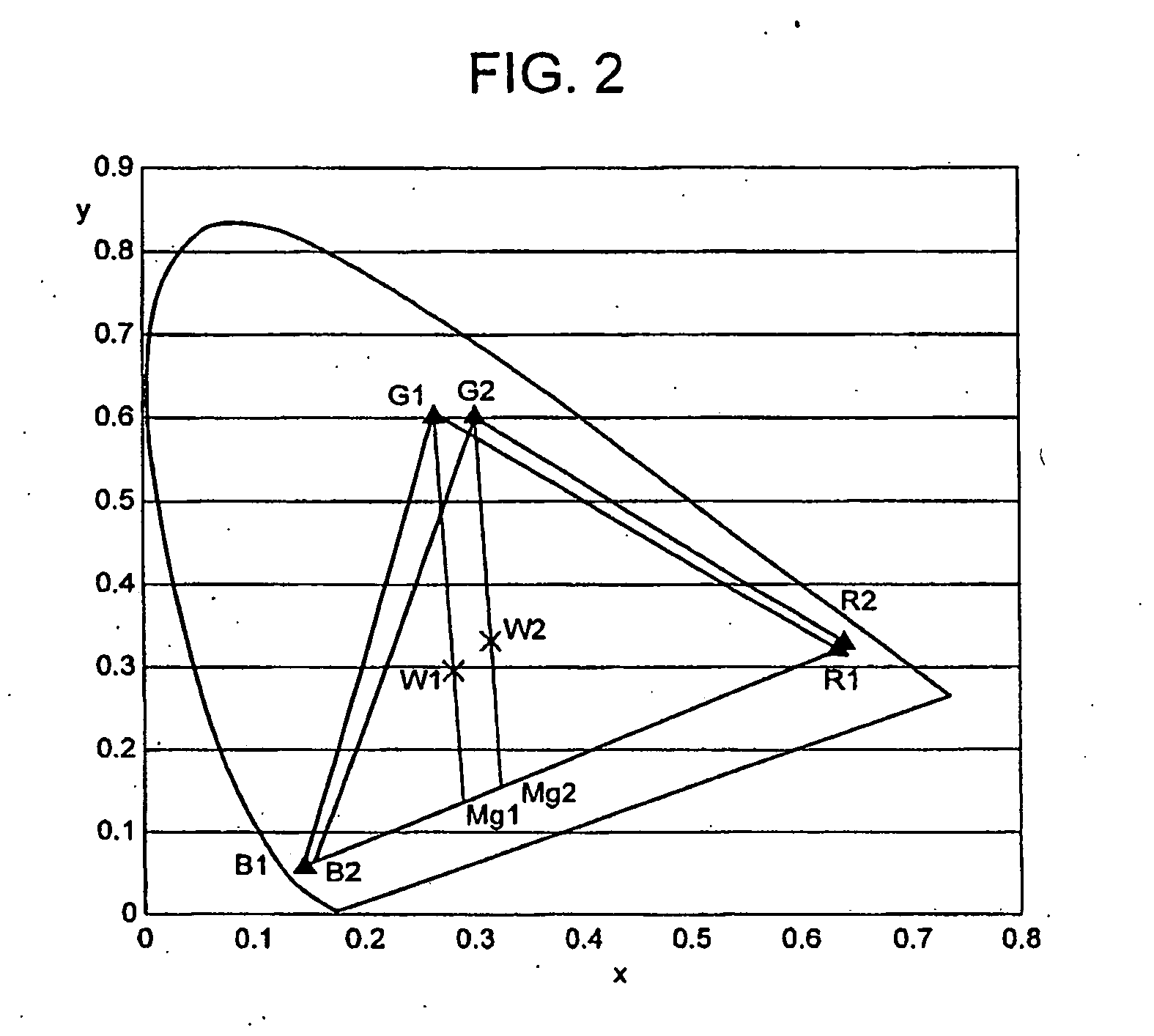
[0044] A first embodiment will be described with reference to FIG. 1 and FIG. 2. FIG. 1 shows the construction of a color conversion unit in the first embodiment. The color conversion unit is a unit corresponding to the adjusting circuit in the image display apparatus. The input image signals to be inputted to the color conversion unit are the RGB signals, which are decoded by the not-shown image signal input unit from the image data coming from the I / F unit 504 of FIG. 5. From the color conversion unit, moreover, the color conversion image output signals are outputted to the not-shown row wire drive unit. The color conversion unit includes the inverse-γ conversion unit 101, a multiplier 103 corresponding to a correction circuit; a linear matrix conversion unit 104 corresponding to a matrix operation circuit, a first register 105, a second register 106, a data bus 107, and an MPU 108 corresponding to the control circuit.
[0045] In FIG. 1, the inverse-γ conversion unit 101 performs a...
second embodiment
[0057] A second embodiment will be described with reference to FIG. 2, FIG. 3 and FIG. 4. FIG. 3 shows the configuration of an image display apparatus according to the second embodiment. In FIG. 3, the display panel 200 is composed of a plurality of electron emitting devices and a fluorescent face for fluorescing when it receives the irradiation of electron beams of the electron emitting devices. When the plural electron emitting elements are excited by the drive signal from the row wire drive unit 203 and the column wire drive units 204, the display panel 200 has its fluorescent face excited with the emitted electron beams by the acceleration voltage from a high-voltage power source 211 so that the image display is performed. These configuration and drive method are omitted here because they are described in detail in Patent Publication 1 (JP-A-6-342636).
[0058] In the embodiment, the image display apparatus is provided with a row wire drive voltage power source 209 for generating ...
third embodiment
[0071] A third embodiment will be described on the configuration, which can make a finer color adjustment.
[0072] The set data in the color reproduction mode 1 are the RGB intensity ratio coefficients (gr_1, gg_1 and gb_1) set with the white color temperature W1 and the color range matrix coefficients (K12_1, K13_1, K21_1, K23_1, K31_1 and K32_1). Moreover, the set data in the color reproduction mode 2 are the RGB intensity ratio coefficients (gr_2, gg_2 and gb_2) set with the white color temperature W2 and the color range matrix coefficients (K12_2, K13_2, K21_2, K23_2, K31_2 and K32_2). At this time, in case a white color temperature Wα intermediate between W1 and W2 is to be displayed, the RGB intensity ratio coefficients (gr_α, gg_α and gb_α) and the color range matrix coefficients (K12_α, K13_α, K21_α, K23_α, K31_α and K32_α) are determined by the interpolating operations of the MPU from the set coefficient of the white color temperature W1 and the set coefficient of the white ...
PUM
 Abstract
Description
Claims
Application Information
 - R&D
- Intellectual Property
- Life Sciences
- Materials
- Tech Scout
- Unparalleled Data Quality
- Higher Quality Content
- 60% Fewer Hallucinations
Browse by: Latest US Patents, China's latest patents, Technical Efficacy Thesaurus, Application Domain, Technology Topic, Popular Technical Reports.
© 2025 PatSnap. All rights reserved.Legal|Privacy policy|Modern Slavery Act Transparency Statement|Sitemap|About US| Contact US: help@patsnap.com


