Convertible projection assembly and method

a technology of projectors and components, applied in the field of rear projection units, can solve the problems of affecting the presentation of information, and affecting the presentation effect, so as to reduce the cost of the system, facilitate the presentation, and facilitate the us

Inactive Publication Date: 2005-08-04
STEELCASE INC
View PDF22 Cites 21 Cited by
  • Summary
  • Abstract
  • Description
  • Claims
  • Application Information

AI Technical Summary

Benefits of technology

[0023] It has been recognized that various common office facility structures can be easily converted from their normal configurations into part of a rear projection system thereby providing a dual function and hence reducing system costs appreciably. More specifically, various common office facility structures can be used to support a display screen, a reflecting member and a projector in functionally operable juxtapositions.
[0024] It has also been recognized that the display screen, reflecting member and projector may be designed to have forms that are relatively easy to handle, are easily portable and that require minimal storage space.

Problems solved by technology

While front projectors are typically easily portable and therefore can be used in many different locations, unfortunately, these system have several shortcomings.
First, the screens used with front projectors typically are relatively large and are not easily portable.
In the case of a front projector, unfortunately, a presenter's presence between the projector and the image results in a shadow being cast on the display screen and temporary loss of at least some of the presented information.
Third, where a projector is portable, when a projector is brought into a room for use, prior to using the projector several power, data and control linkages are typically required.
While projector manufacturers have taken steps to streamline the projector linkage tasks, these tasks are often time consuming and are generally viewed as tedious and as an impediment to use.
Fourth, where a front projector is used, often, there is a minimum projector-to-screen distance requirement that cannot be met in small spaces such as modest offices or cubicles.
Unfortunately, while rear projection systems provide many advantages, rear projection systems also have several shortcomings.
First, because rear projection systems require a dedicated housing structure for defining the projection path of images from a projector, rear projection systems are typically relatively bulky.
Because of their size, a relatively large space is typically required to store a rear projection system.
Second, because of their large size, while most rear projection systems may fit within relatively small rooms, such systems are rarely used in small rooms.
For instance, while a rear projector may fit within a standard sized cubicle, such systems would leave little room for a presenter and an audience within the cubicle and therefore are only rarely used within such a small space.
Third, in addition to being of a large size, many rear projectors are also relatively heavy so that, despite being transportable, most rear projectors are only rarely moved from one location to another for remote use.
In fact, because of their bulkiness, despite requiring less space than typical front projection systems, in many cases rear projection systems are rarely moved within even a single facility.
Fourth, because rear projection systems require a support structure, a housing assembly and often one or more reflecting mirror assemblies, the overall costs of these systems is relative high.
Fifth, because rear projection systems are typically integrated into a complete housing, many people do not understand how rear projection systems operate.
While lack of operational knowledge may not appear to be an important concern at first blush, it is believed that, as with many emerging technologies, lack of operational knowledge has, in the past, lead to underutilization of rear projection systems.
Sixth, while some rear projection systems include a screen surface suitable for use as a whiteboard, in most cases projection screens are not employed for this purpose when conventional whiteboard functionality without projection is required.
While low profiles increase stability, such profiles typically reduce the height of the projection screen and thus reduce the usefulness of a system for presenting information to large audiences.
A related limitation is that the height of a rear projection screen typically is not adjustable.

Method used


Image

  • Convertible projection assembly and method
  • Convertible projection assembly and method
  • Convertible projection assembly and method

Examples


first embodiment

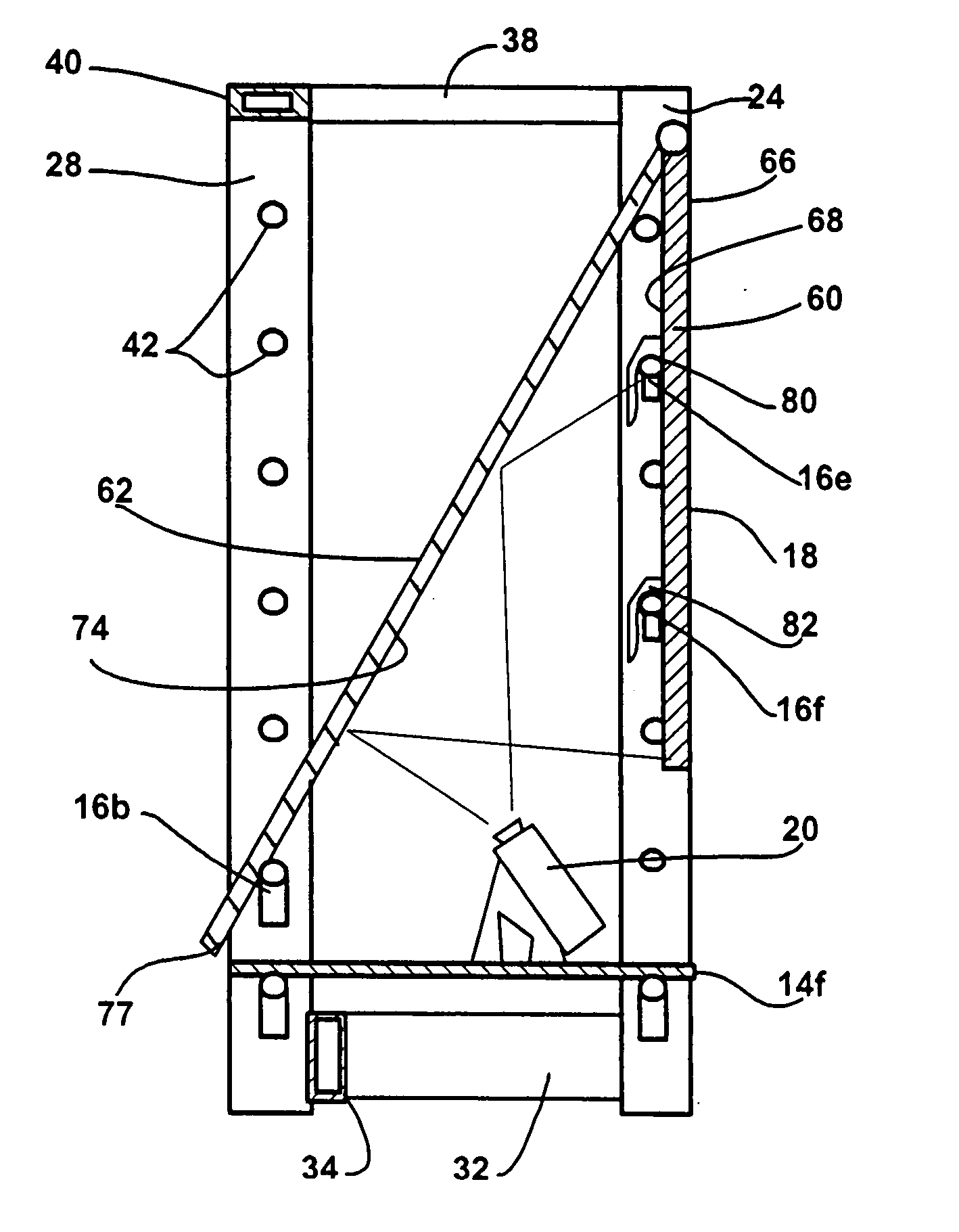
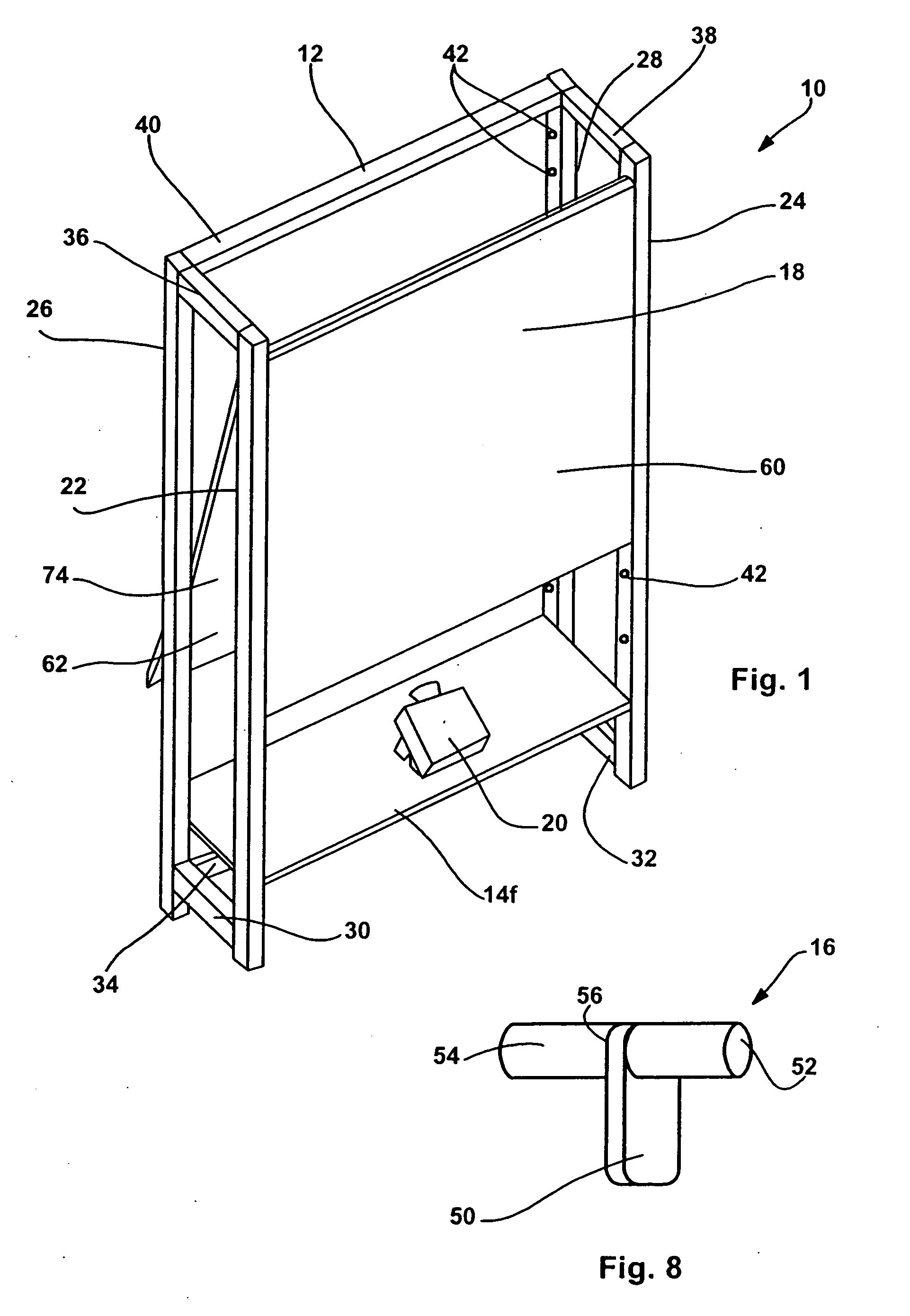
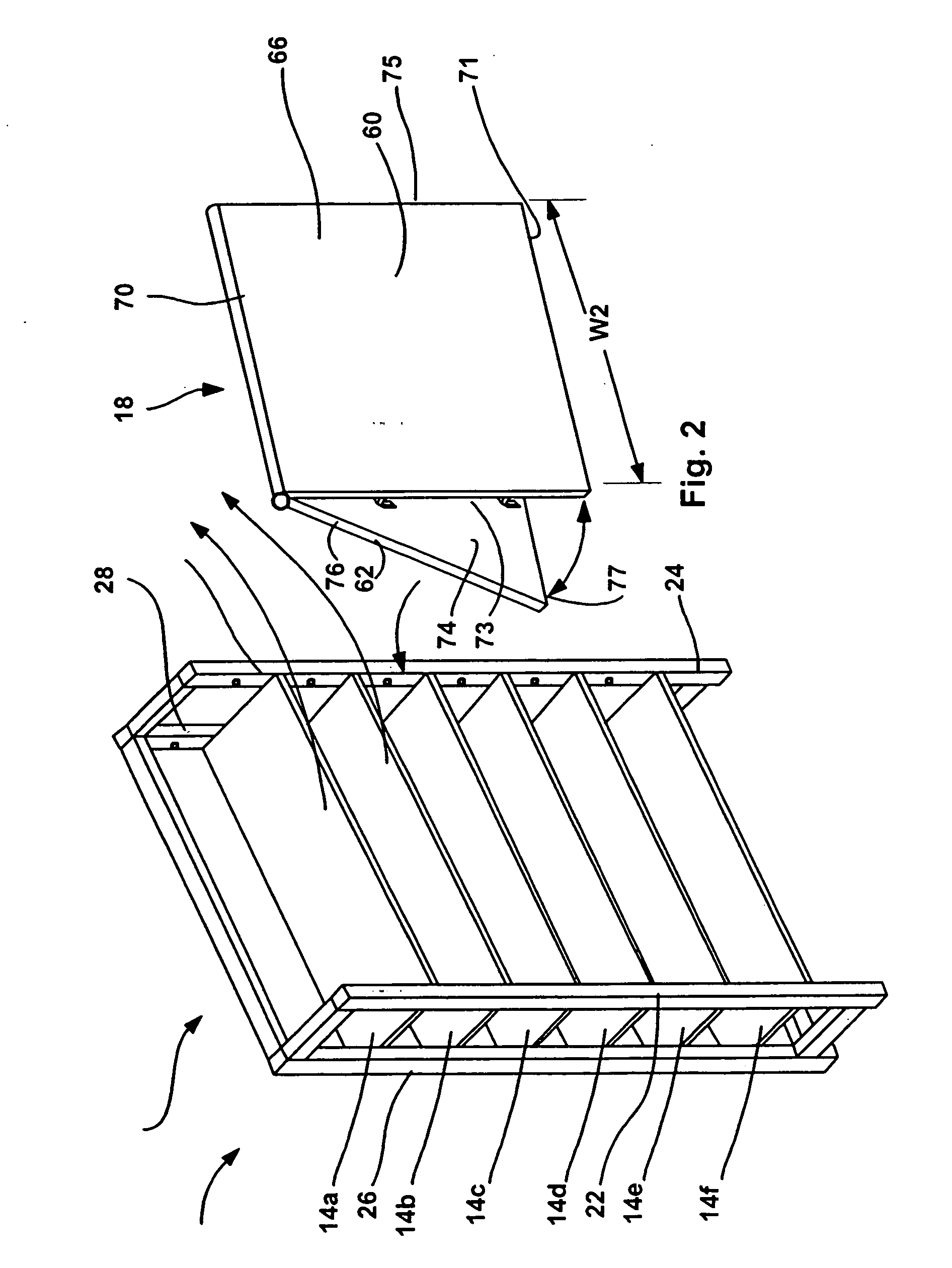
[0069] Referring now to the drawings wherein like reference numeral correspond to similar elements throughout the several views and, more specifically, referring to FIGS. 1 through 8, a first embodiment of the present invention will be described in the context of a shelf-projection assembly 10 that, as its label implies, is convertible between a shelving configuration (see FIG. 2) and a rear projecting configuration (see FIG. 1). To this end, shelf-projection assembly 10 includes a support structure generally identified by numeral 12, a plurality of shelf members 14a through 14f (see FIG. 2) (i.e., accessory members), a plurality of pin assemblies, several of which are identified by numeral 16, 16a, 16b, etc., in the figures, a screen-reflector assembly 18 and a projector unit 20.

[0070] Support structure 12 is formed of a rigid material such as steel or aluminum. In the illustrated embodiment, structure 12 includes four upright or vertical support members 22, 24, 26 and 28, and six...

second embodiment

[0094] Referring now to FIGS. 9 through 13, a second embodiment of the present invention is illustrated. This second embodiment is similar to the first embodiment in many respects and therefore, in the interest of simplifying this explanation, only differences between the first and second embodiments will be described here in detail. Components in this second embodiment that are similar to the components described above with respect to the first embodiment are identified by similar numbers herein followed by a prime (i.e., “′”).

[0095] In general, there are three primary differences between the first and second embodiments. First, instead of providing a single assembly 18 that includes both the screen member and the reflecting member, in this second embodiment, the screen member is separate from the reflecting member and the screen member and reflecting member mount separately to the support structure 12. Second, the mounting structure for the screen member in this second embodiment...

third embodiment

[0104] According to a third embodiment of the present invention, a screen member similar to the screen members described above may be mounted on tracks to be moved laterally to any of several different positions with respect to an extended shelving assembly. Here, the screen member, when not being used for displaying projected images, may be used as a sliding door member or the like to hide materials therebehind.

[0105] Referring now to FIGS. 14 through 16, a third embodiment 10″ of the present invention including a sliding screen member 60″ is illustrated. In this third embodiment, many of the components are substantially similar to the components described above with respect to the first two embodiments and therefore, in the interest of simplifying this explanation, will not be described here again in detail. Here, it should suffice to say that similar components are identified by similar numbers followed by a double prime (i.e., “″”).

[0106] The primary differences between this t...


PUM


Abstract

A convertible projection assembly and method, the assembly including a support structure, a translucent screen member including a viewing front surface and an oppositely facing rear surface, the screen member releasably mountable to the support structure and a reflecting member forming an internal surface and an oppositely facing external surface, the internal surface of the reflecting member at least in part forming a reflecting surface, the reflecting member releasably mounted to the support structure such that the reflecting surface at least in part faces the rear surface of the screen member.

Description

CROSS-REFERENCE TO RELATED APPLICATIONS [0001] Not applicable. STATEMENT REGARDING FEDERALLY SPONSORED RESEARCH OR DEVELOPMENT [0002] Not applicable. BACKGROUND OF THE INVENTION [0003] This invention relates generally to rear projection units and more specifically to a convertible assembly that projects an image through a projecting space and onto a screen when the assembly is configured to provide a projecting function and that may use the projecting space for a different function when the assembly is configured to provide a non-projecting function. [0004] This section of this document is intended to introduce various aspects of art that may be related to various aspects of the present invention described and / or claimed below. This section provides background information to facilitate a better understanding of the various aspects of the present invention. It should be understood that the statements in this section of this document are to be read in this light, and not as admissions...

Claims


Application Information

Patent Timeline
Patent Type & Authority Applications(United States)
IPC IPC(8): G09G3/28
CPCG03B21/00
Inventor FELDPAUSCH, THOMAS G.MARTIN, KIRT D.RUITER, JOEL T.
Owner STEELCASE INC
Why Eureka
Try Eureka