Light modulating engine

a technology of light modulating engine and light source, which is applied in the field of light illumination apparatus, can solve the problem of limited modulating speed and achieve the effect of optimizing the scanning area

Inactive Publication Date: 2005-08-04
SIGN TRONIC
View PDF7 Cites 49 Cited by
  • Summary
  • Abstract
  • Description
  • Claims
  • Application Information

AI Technical Summary

Benefits of technology

[0029] According to the invention it has been recognized that a very close positioning of the light modulating arrangements facilitates an improved overall scanning speed in the sense that the effec...

Problems solved by technology

A problem of the prior art is that the obtainable modulating speed is somewhat limited due to the nature ...

Method used


Image

  • Light modulating engine
  • Light modulating engine
  • Light modulating engine

Examples


Embodiment Construction

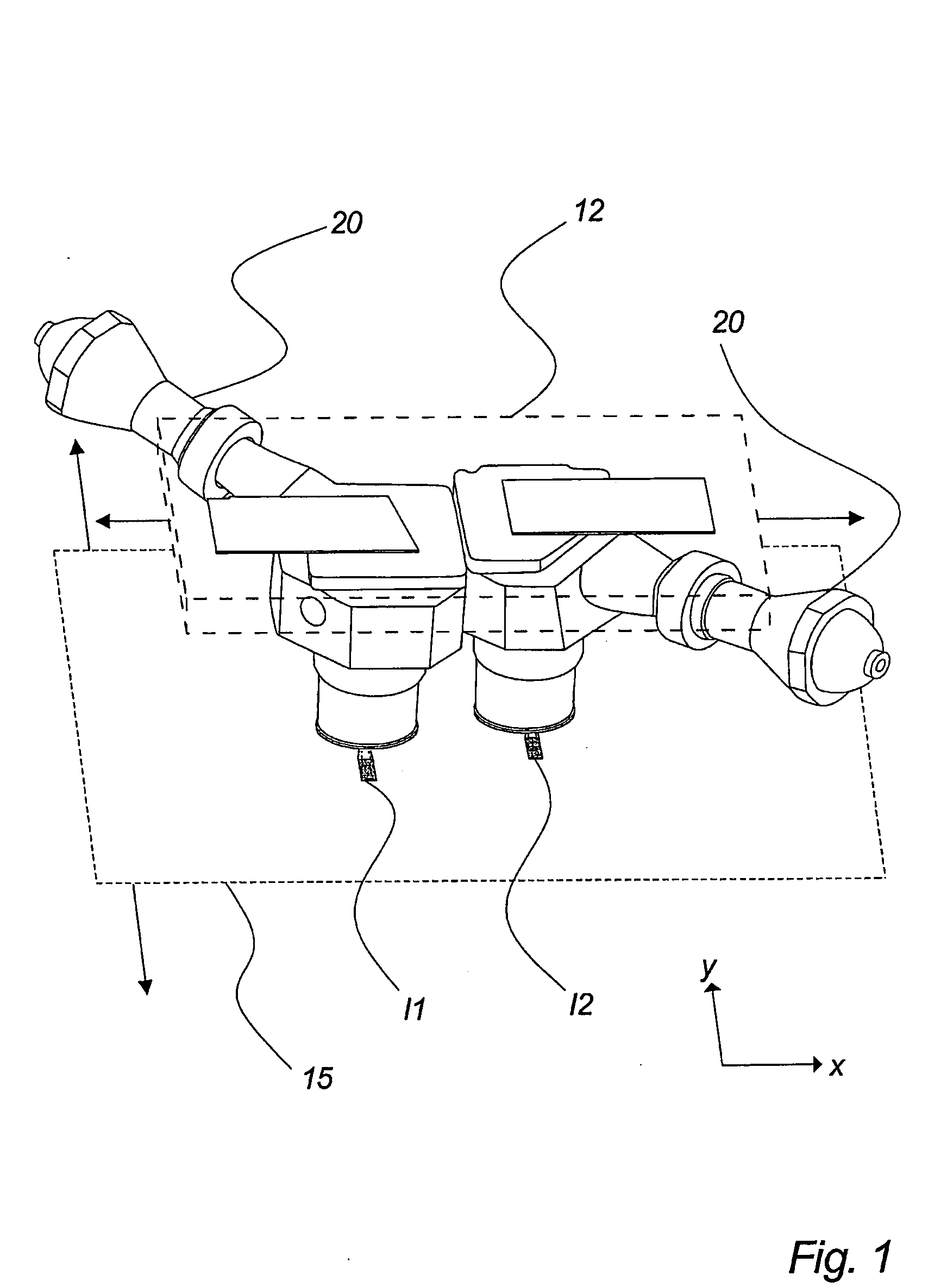
[0060]FIG. 1 illustrates a view of a few main components of an exposure system, according to an advantageous embodiment of the invention.

[0061] The illustrated system comprises an exposure head 12 comprising two illumination arrangements 20 arranged for illumination of an illumination surface 15. The exposure head 12 is suspended in a suspension (not shown). The suspension facilitates movement in the direction of the arrows under control by suitable electronic circuits (not shown).

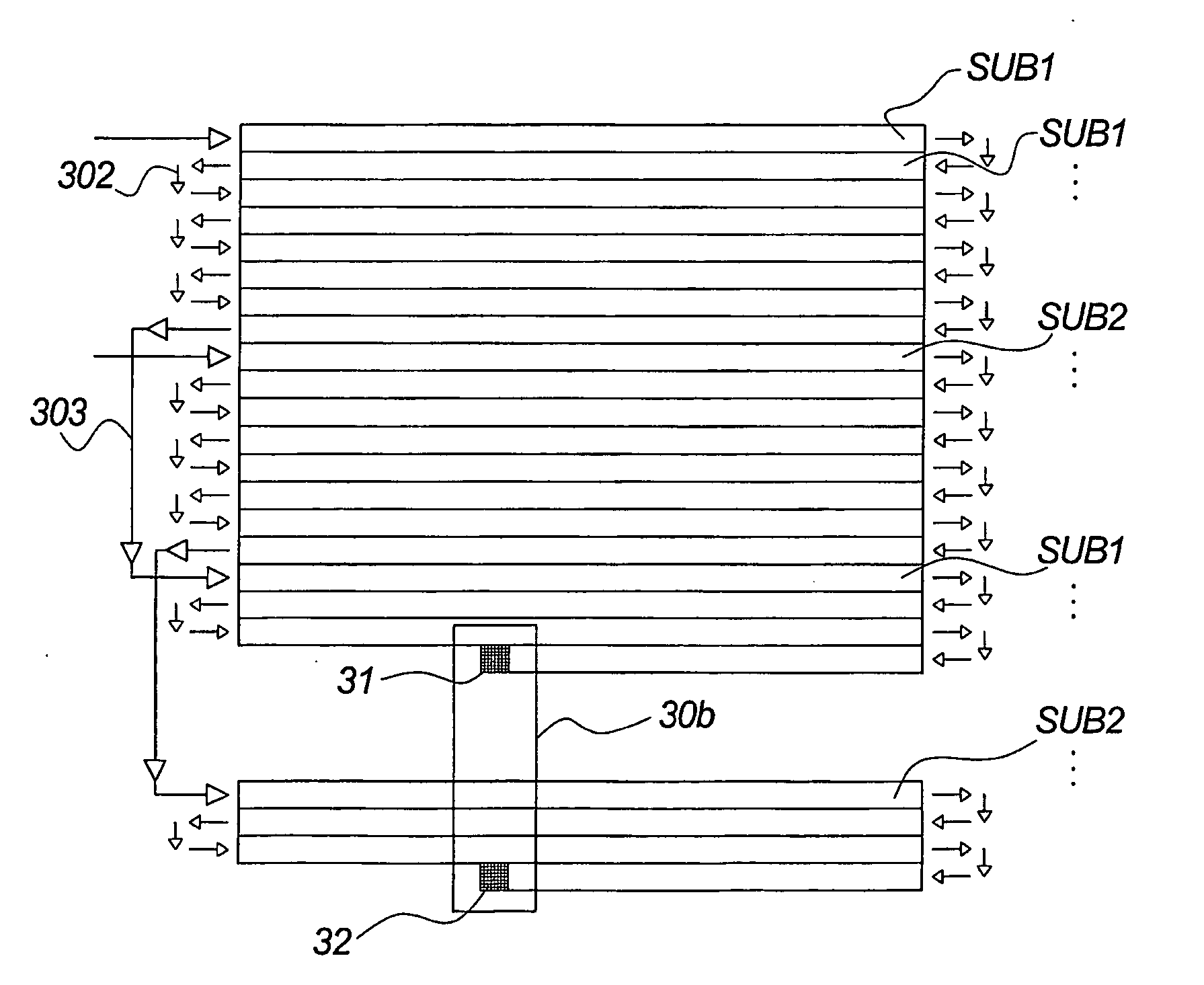
[0062] For illustrative purposes, two illumination areas I1, I2 illuminated by the spatial light modulators (e.g. DMD chips) arranged in the illumination arrangements 20 are indicated on the illumination surface. The illumination areas I1 and I2, may e.g. comprise 1024×768 (XGA) pixels or 1280×1024 pixels (SXGA) if applying e.g. TI DMD-chips. The modulated pixels will, if applying a scanning movement, be switched dynamically from row to row (or column to column) thereby applying several pixels (e.g. a co...


PUM


Abstract

The invention relates to a light illumination apparatus comprising at least one exposure head (12) and at least two light modulating arrangements (20), each of said two light modulating arrangements (20) comprising a spatial light modulator (31, 32) and an associated light emitter arranged for illumination of an illumination surface (15) via said spatial light modulator (31, 32), each of said two light modulating arrangements (20) being digitally controlled, said apparatus comprising means for performing a relative movement between said at least one exposure head and said illumination surface (15) in at least one direction (x;y).

Description

FIELD OF THE INVENTION [0001] The present invention relates to a light illumination apparatus according to claim 1. BACKGROUND OF THE INVENTION [0002] A typical light illumination apparatus comprises an arrangement adapted for illuminating a light sensitive material. Such material may e.g. comprise printing plates, materials adapted for rapid prototyping, film, etc. The illuminating is performed for the purpose of obtaining certain changes of properties of the illuminated material. Such illumination may thus e.g. result in the establishment of an image on the illuminated material or a certain structure. [0003] In order to obtain the desired illumination, light must be modulated. One prior art method of modulating light transmitting to an illumination surface is to apply a single or multiple beam laser, which may be modulated when performing a scanning movement over the illumination surface. [0004] Another and more recent way of illuminating an illumination surface is to apply a so-c...

Claims


Application Information

Patent Timeline
IPC IPC(8): G03B21/00G03F7/20H04N5/74
CPCG03F7/2057G03F7/70058H04N5/7416G03F7/70283G03F7/70291G03F7/70275G02B26/02G02B26/10
Inventor GLENT-MADSEN, HENRIK
Owner SIGN TRONIC
Why Eureka
Try Eureka