Computation of decision feedback equalizer coefficients with constrained feedback tap energy

a decision feedback equalizer and tap energy technology, applied in the field of digital communication, can solve the problems of equalizers suffering from noise enhancement, interfering between subject symbols and a plurality of symbols, and channel also introducing noise into symbols

Inactive Publication Date: 2005-08-04
AVAGO TECH INT SALES PTE LTD
View PDF11 Cites 14 Cited by
  • Summary
  • Abstract
  • Description
  • Claims
  • Application Information

AI Technical Summary

Problems solved by technology

In many communication systems, such as terrestrial based wireless communication systems, satellite based communication systems, cable based communication systems, etc., and the channel distorts the transmitted symbols, from the perspective of the receiver, causing interference between a subject symbol and a plurality of symbols surrounding the subject symbol.
The channel also introduces noise into the symbols prior to their receipt.
Linear equalizers suffer from noise enhancement, which can become damaging for low SNR.
The feedback nature of a DFE makes it vulnerable to error propagation in the feedback equalizer (FBE).
The probability of error propagation increases with the energy of the feedback taps.
A critical factor in increasing the effectiveness of these equalizers is the complexity of optimal equalizer coefficient computation.
However, the overall procedures for calculation of the DFE (FBE and FFE) coefficients have the following problems: 1.
These equations are difficult to implement from the perspective of integrated circuit design.
As is generally known, the use of a DSP processor in a real-time communication system application is severely constricts system throughput.
In other words, they require the use of a relatively large number of complex multiplies.
The prior art techniques cannot use a different delay a of the equalizer.
Such matrix inversion requires the greater of L3 or N3 multiplications and cannot be accomplished timely enough to allow a prior art transceiver to compute LE coefficients based upon a channel estimate.
Oftentimes, such convergence in training could not be accomplished to meet the requirements of rapidly changing channels.
However, considerations of noise enhancement and error propagation often change over time in many communication systems.

Method used


Image

  • Computation of decision feedback equalizer coefficients with constrained feedback tap energy
  • Computation of decision feedback equalizer coefficients with constrained feedback tap energy
  • Computation of decision feedback equalizer coefficients with constrained feedback tap energy

Examples


Embodiment Construction

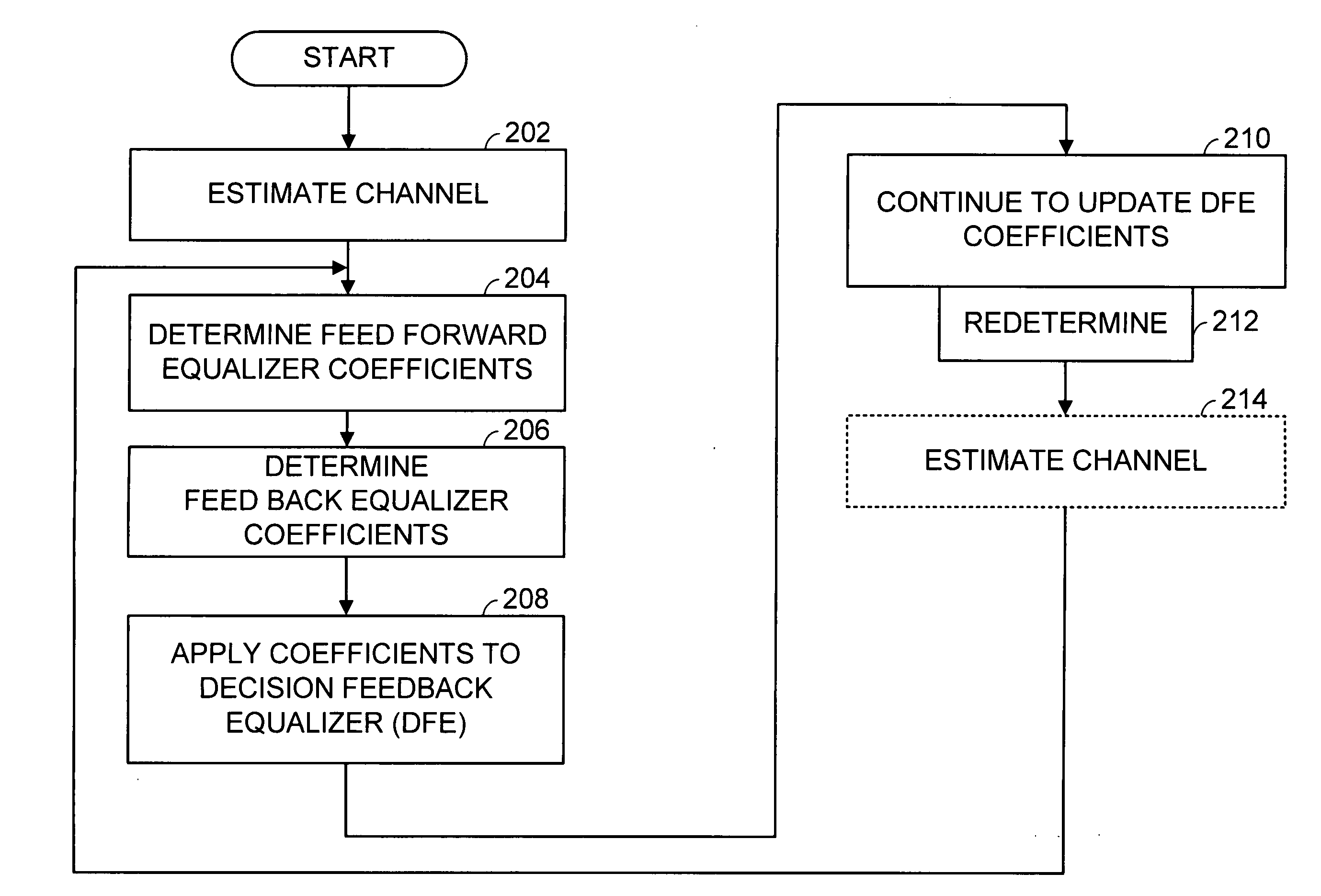
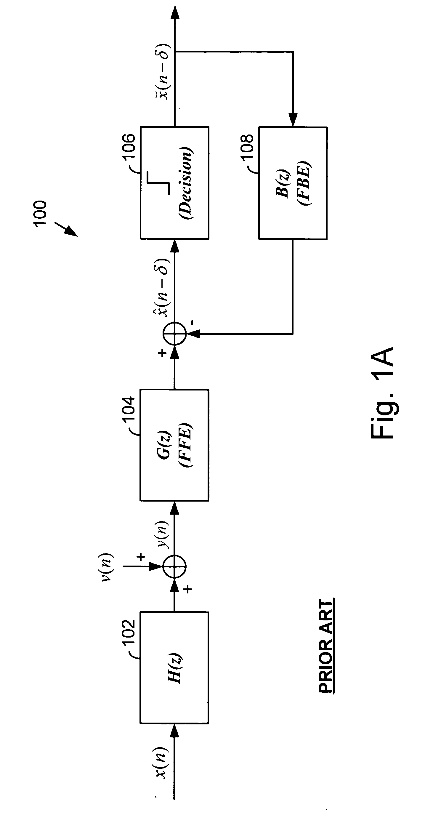
[0038]FIG. 2 is a logic diagram generally illustrating operation according to the present invention in determining Decision Feedback Equalizer (DFE) coefficients and in applying such coefficients to a DFE. The operations of the present invention are performed by a processor, such as a Digital Signal Processor (DSP), or other circuitry present within a receiver that determines DFE coefficients to be applied to a DFE, also resident in the receiver. The DFE operates upon samples of a received signal in an attempt to remove channel effects from the samples so that digital data may be extracted from the samples. The structure and operation of DFEs, one of which was illustrated in FIG. 1A, are generally known and will not be further described herein except as they relate to the present invention.

[0039] The operations of the present invention will be first performed by a processor, tap computer, DSP, or other receiver device, to determine initial DFE coefficients to be used in subsequent ...


PUM


Abstract

Directly computing Feed Forward Equalizer (FFE) coefficients and Feed Back Equalizer (FBE) coefficients of a Decision Feedback Equalizer (DFE) from a channel estimate. The FBE coefficients have an energy constraint. A recursive least squares problem is formulated based upon the DFE configuration, the channel estimate, and the FBE energy constraint. The recursive least squares problem is solved to yield the FFE coefficients. The FFE coefficients are convolved with a convolution matrix that is based upon the channel estimate to yield the FBE coefficients. A solution to the recursive least squares problem is interpreted as a Kalman gain vector. A Kalman gain vector solution to the recursive least squares problem may be determined using a Fast Transversal Filter (FTF) algorithm.

Description

CROSS REFERENCES TO RELATED APPLICATIONS [0001] The present application is a continuation-in-part of U.S. Regular Utility application Ser. No. 10 / 956,172, filed Oct. 1, 2004, which is a continuation-in-part of U.S. Regular Utility application Ser. No. 10 / 044,013, filed Oct. 26, 2001, which claims priority to U.S. Provisional Application Ser. No. 60 / 322,994, filed Sep. 18, 2001. The present application is also a continuation in part of U.S. Regular Utility application Ser. No. 10 / 154,947, filed May 24, 2002, which claims priority to U.S. Provisional Application Ser. No. 60 / 339,253, filed Oct. 26, 2001 and which is a continuation-in-part of U.S. Regular Utility application Ser. No. 10 / 044,013, filed Oct. 26, 2001, which claims priority to U.S. Provisional Application Ser. No. 60 / 322,994, filed Sep. 18, 2001, All of these applications are incorporated herein by reference in their entirety.BACKGROUND OF THE INVENTION [0002] 1. Field of the Invention [0003] This invention relates general...

Claims


Application Information

Patent Timeline
Patent Type & Authority Applications(United States)
IPC IPC(8): H04L1/06H04L25/03
CPCH04L1/06H04L2025/03605H04L2025/0349H04L25/03057
Inventor YOUSEF, NABIL R.MERCHED, RICARDO
Owner AVAGO TECH INT SALES PTE LTD
Why Eureka
Try Eureka