Apparatus for supporting compressor

Active Publication Date: 2005-08-04
LG ELECTRONICS INC
View PDF19 Cites 14 Cited by
  • Summary
  • Abstract
  • Description
  • Claims
  • Application Information

AI Technical Summary

Benefits of technology

[0011] Therefore, an object of the present invention is to provide a support apparatus capable of improving support performance and vibration preventing

Problems solved by technology

However, the conventional support a

Method used


Image

  • Apparatus for supporting compressor
  • Apparatus for supporting compressor
  • Apparatus for supporting compressor

Examples


first embodiment

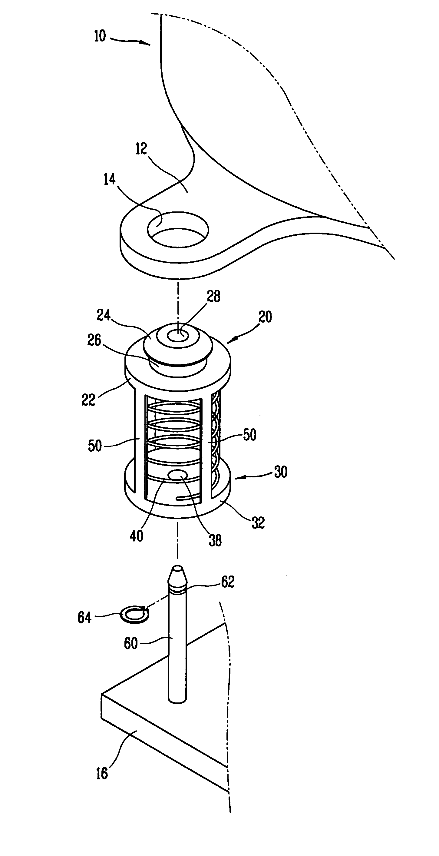
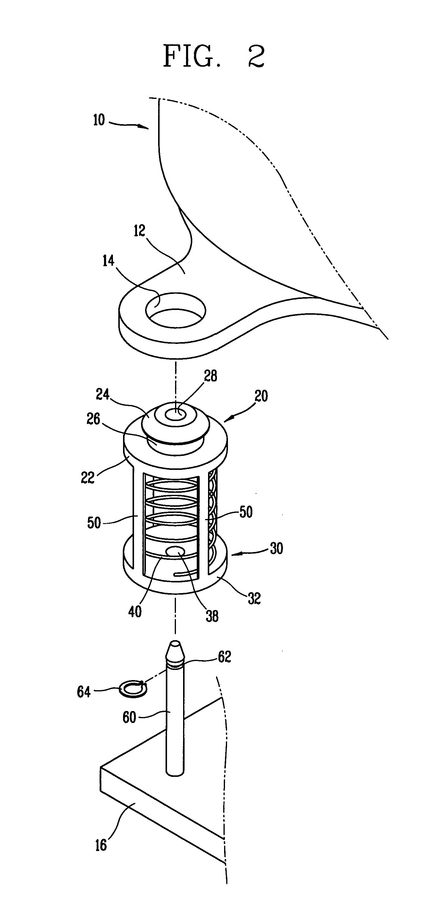
[0025] As shown in FIGS. 2 to 4, a support apparatus in accordance with a first embodiment of the present invention includes: a first support member 20 connected to a bracket 12 extended from one side of a compressor 10 by being inserted at a coupling hole 16 formed at the bracket 12; a second support member 30 disposed at a predetermined interval from the first support member 20 and fixed to a base 16 to which the compressor 10 is supported; a fixing shaft 60 penetrating central portions of the first support member 20 and the second support member 30 and fixed to the base 16; a spring 40 disposed between the first support member 20 and the second support member 30 and having both ends contacted with the first support member 20 and the second support member 30, respectively to be supported thereby, for supporting the compressor 10 and absorbing vibration of the compressor 10; and at least one connection member 50 installed between the first support member 20 and the second support m...

second embodiment

[0040] Hereinafter, with reference to FIG. 5, a support apparatus in accordance with a second embodiment of the present invention will now be described. The same reference numerals will be given to the same parts as the above-mentioned first embodiment, and descriptions thereabout will now be omitted.

[0041] As for a support apparatus in accordance with the second embodiment of the present invention, spring support grooves 25 and 35 in which parts of both ends of the spring 40 are respectively inserted are respectively formed at surfaces of the spring support portions 22 and 32 of the first and second support members 20 and 30 for respectively supporting both ends of the spring 40, which are contacted with both ends of the spring 40.

[0042] When projected on plane, the spring support grooves 25 and 35 are formed in a ring shape so that both ends of the spring 40 are inserted therein. Preferably, a width of the spring support groove 25, 35 is formed to be the same as or smaller than ...

third embodiment

[0046] Hereinafter, a support apparatus in accordance with a third embodiment of the present invention will now be described with reference to FIG. 6. The same reference numerals will be given to the same parts as the above-mentioned embodiments, and descriptions thereabout will now be omitted.

[0047] As for a support apparatus in accordance with the third embodiment of the present invention, a spring support groove 25 in which a part of one end of the spring 40 is inserted is formed at a surface of a spring support portion 22 of a first support member 20, which is contacted with one end of the spring 40. In order to prevent movement of the spring 40, a protruded portion 21 protruded in a direction that the first and second support members 20 and 30 face into each other is formed from the spring support groove 25 toward a central axis (C) of the spring 40.

[0048] In addition, a spring support groove 35 in which a part of the other end of the spring 40 is inserted is formed at a surf...


PUM


Abstract

A support apparatus comprises: a first support member connected to the compressor; a second support member disposed at a predetermined interval from the first support member and fixed to a base; a spring disposed between the first support member and the second support member, of which both ends are contacted with the first support member and the second support member to be supported thereby; and at least one connection member connecting the first support member and the second support member so that the spring is not separated from between the first support member and the second support member. Accordingly, the spring is prevented from being moved or buckled by vibration of the compressor, or both ends of the spring are prevented from being detached from the support members, so that support performance and vibration preventing effect for the compressor can be improved.

Description

BACKGROUND OF THE INVENTION [0001] 1. Field of the Invention [0002] The present invention relates to a support apparatus for supporting compressor, and more particularly, to a support apparatus capable of improving support performance and vibration preventing effect. [0003] 2. Description of the Background Art [0004] As shown in FIG. 1, a conventional support apparatus for supporting a compressor includes a first support member 120 connected to a bracket 12 extended from one side of a compressor 10 by being inserted in a coupling hole 14 formed in the bracket 12; a second support member installed at a base 16 to which the compressor 10 is supported at a predetermined interval from the first support member 120; a fixing shaft 60 penetrating each central portion of the first support member 120 and the second support member 130 and fixed to the base 16; and a spring 140 interposed between the first support member 120 and the second support member 130, for supporting the compressor 10 a...

Claims


Application Information

Patent Timeline
IPC IPC(8): F25D19/00F04B17/00F04B35/00F04B39/00F04C29/00F16F3/10F16F7/104F16F15/04
CPCF04B39/0044F04B39/14F25B2500/13F25D19/00F25D23/006
Inventor YUN, YOUNG-HOON
Owner LG ELECTRONICS INC
Why Eureka
Try Eureka