
Gastric aspirate intestinal feeding tube

a technology of gastrointestinal aspiration and feeding tube, which is applied in the field of multilumen flexible gastrointestinal tube, can solve the problems of inability to safely carry out feeding and aspiration simultaneously, contribute to morbidity and mortality in such patients, and achieve the effect of limiting irritation of the oral-nasal cavity

Inactive Publication Date: 2005-08-04
WOOD SCOTT DOUGLAS
View PDF47 Cites 47 Cited by
  • Summary
  • Abstract
  • Description
  • Claims
  • Application Information

AI Technical Summary

Problems solved by technology

However, feeding and aspiration cannot be done simultaneously.
These patients often undergo procedures requiring them to be placed in a supine position, which generally cannot safely be done without first emptying the gastric contents to prevent unwanted aspiration.
If high residuals remain unchecked, unwanted aspiration of feeds and medication into the lungs may occur, which could result in pneumonia.
Aspiration pneumonia and its associated complications are major contributors of morbidity and mortality in such patients.
Although some G-tubes have added a vent port within the main tube to attempt to prevent mucosal damage during continuous or intermittent suction, because the tube is firm, it can often irritate the nasal and oral mucosa, resulting in patient discomfort.
G-tube use may cause a significant increase in the incidence of acute sinusitis, nasal ulceration, and other associated complications.
Because the distal end of a G-tube is in the stomach, impaired or delayed gastric emptying can be a major limiting factor in the amount of feeds that can be provided.
However, the structure and design of the duodenal feeding tube typically does not provide for checking residual volumes within the stomach.
Although significant gastric residuals are less likely when the tube is properly inserted with the distal end past the pyloric sphincter and into the duodenum, severe and sometimes life-ending complications may occur because of the inability to check for gastric residuals.
In addition, tube migration back into the stomach may occur and can go unnoticed until unwanted aspiration occurs.
Duodenal feeding tubes also typically fail to provide a way to assess the quality of gastric secretions, because the outlets for feeding are in the duodenum, not in the stomach.

Method used


Image

  • Gastric aspirate intestinal feeding tube
  • Gastric aspirate intestinal feeding tube
  • Gastric aspirate intestinal feeding tube

Examples


Embodiment Construction

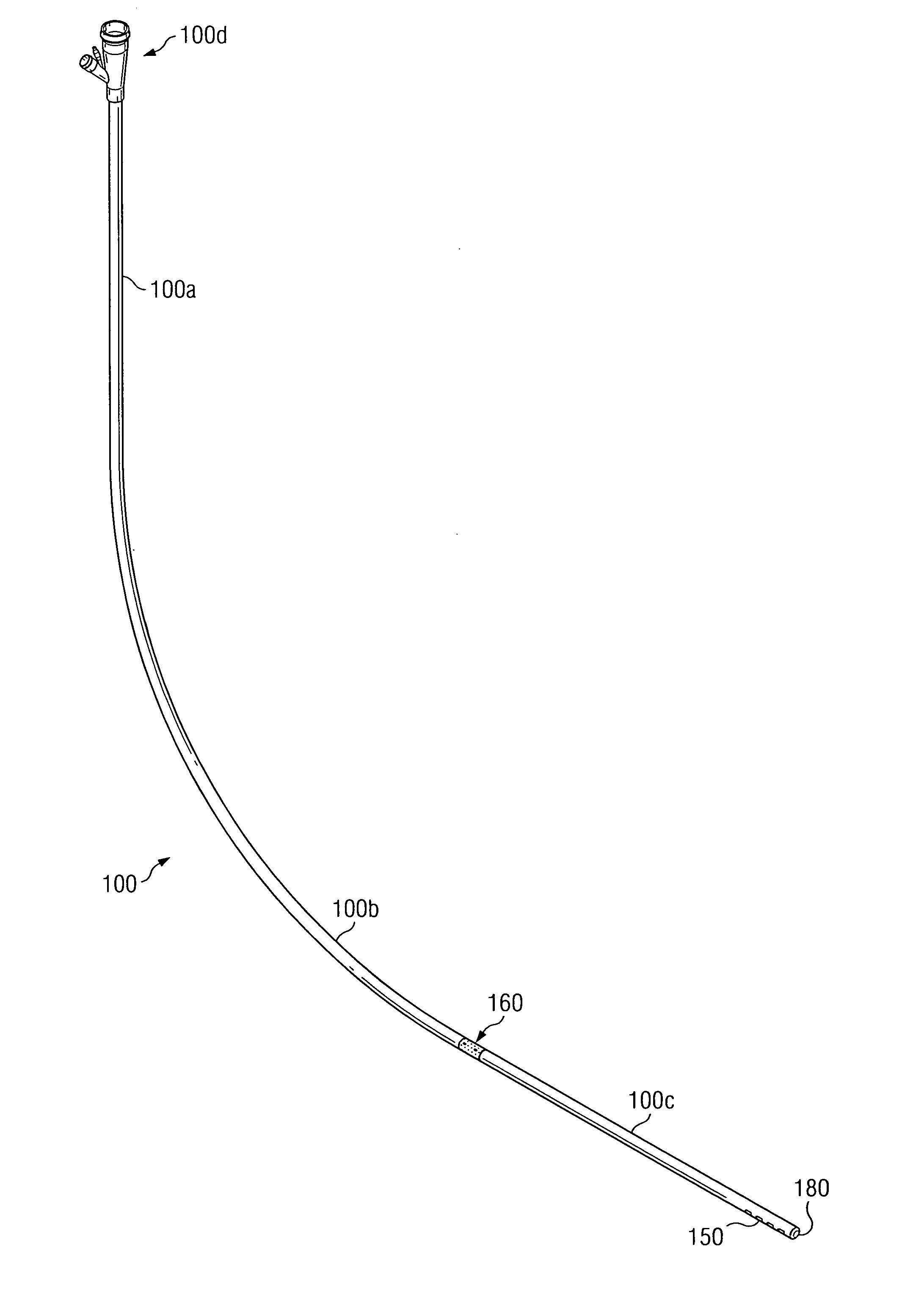
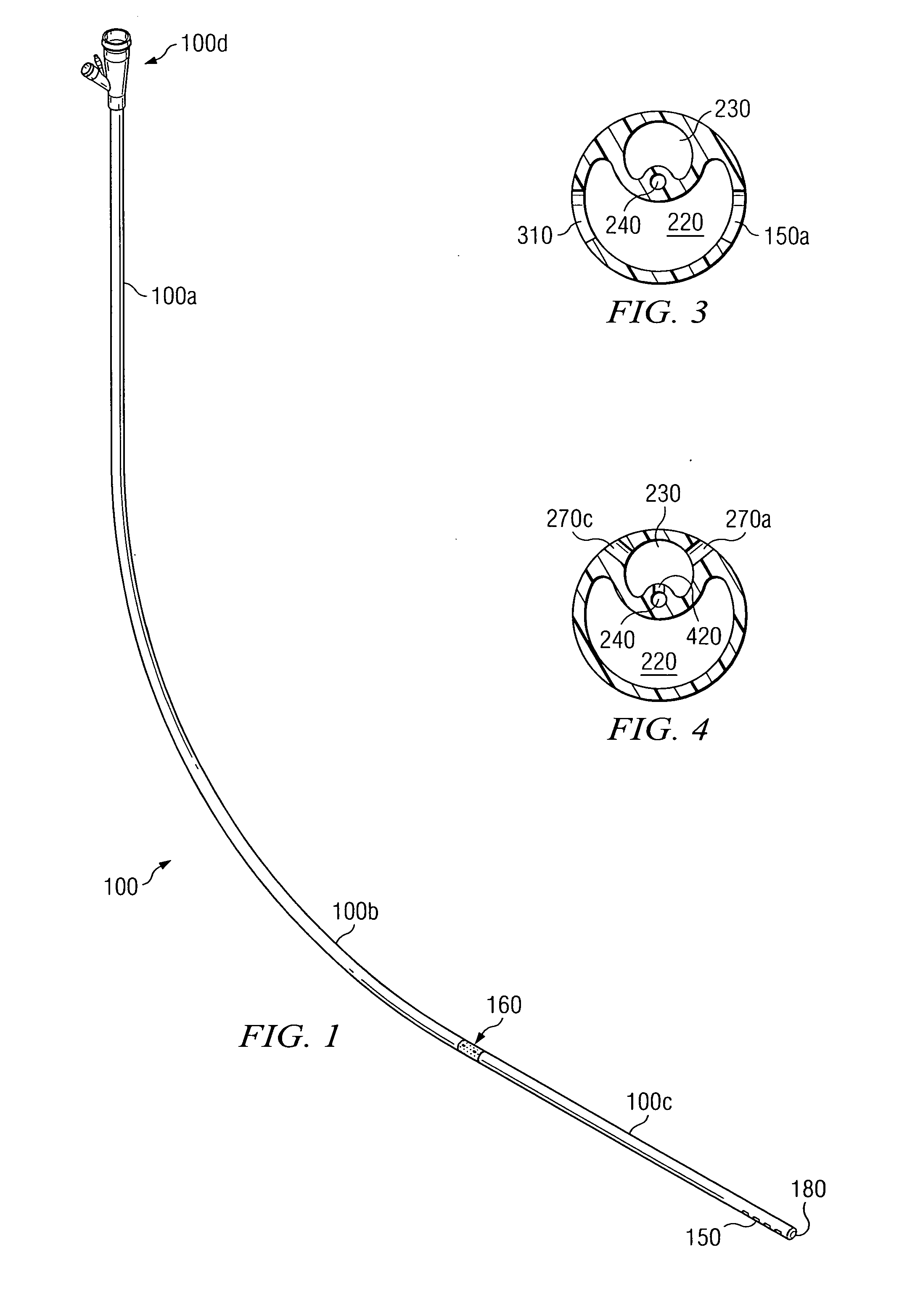
[0024] Referring to the drawings, and in particular FIG. 1, the medical intubation device 100 of the preferred embodiment of this invention is illustrated. The intubation device may be described generally as having three sections. A first section 100a is the upper section and includes an adaptor or fitting 100d illustrated in more detail in FIGS. 5 and 6.

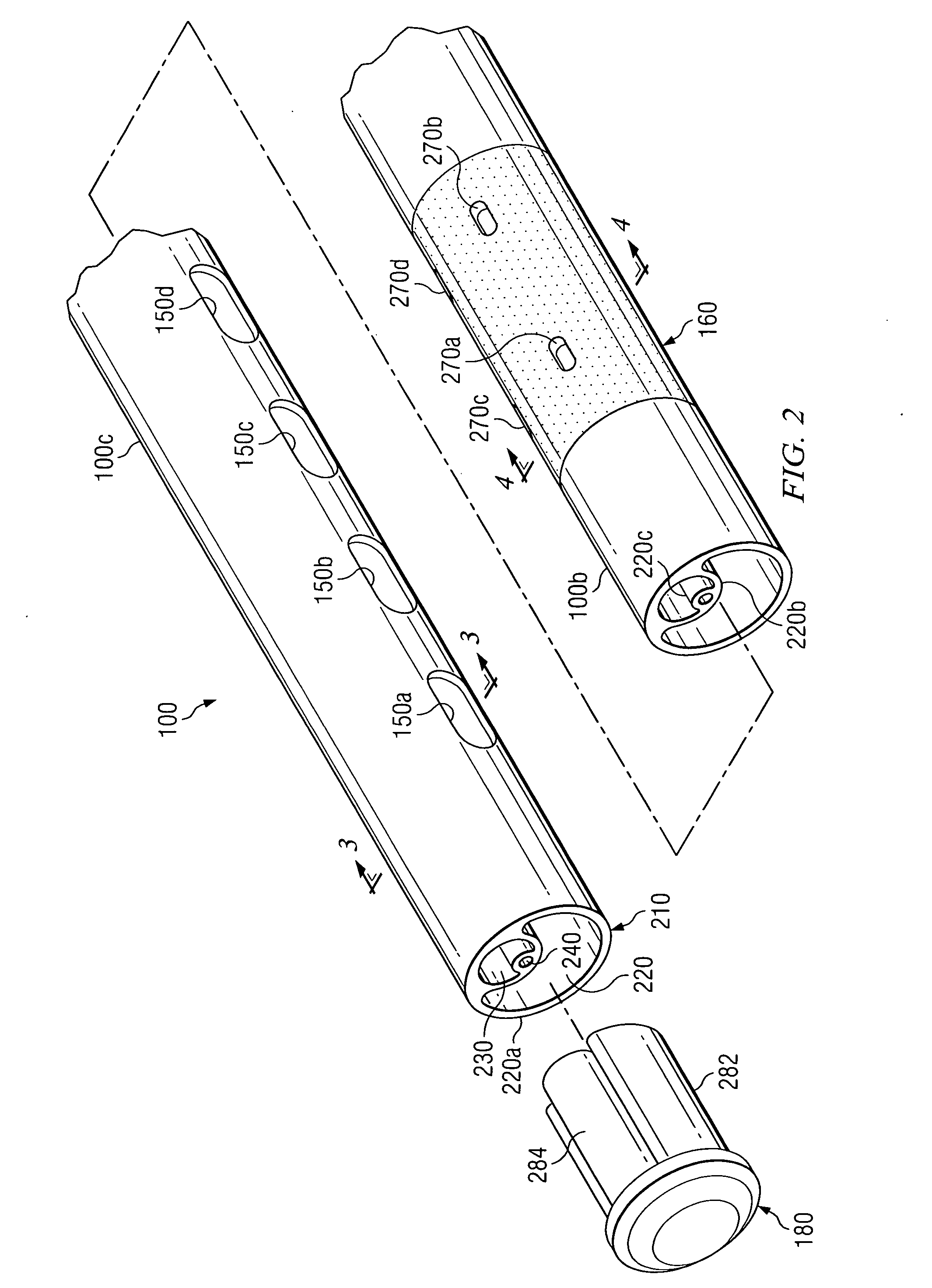
[0025] The second section or intermediate section 100b includes a radio-opaque or other marker 160 shown in detail in FIG. 2, and the distal or insertion section 100c includes openings 150 for delivery of sustenance and medicines into the duodenum. The distal section 100c typically terminates at the distal end with a weighted member 180 shown in detail in FIG. 2.

[0026] Turning now to FIG. 2, a perspective view shows portions of sections 100b and 100c of a preferred embodiment of the medical intubation tube 100. Section 100c is proximal to an insertion or distal end 210 of the tube 100, illustrating a preferred configuration of a f...


PUM


Abstract

A medical intubation device for delivering tube feeds into the duodenum or other intestinal area while aspirating the stomach of a patient is inserted through the patient's oral-nasal cavity. A first lumen of a tubular assembly allows delivery of fluids through outlets into the intestines. A second lumen of the tubular assembly interior to the first lumen provides aspiration through outlets into the stomach. A third lumen of the tubular assembly interior to the second lumen provides ventilation of the second lumen. A weighted member can be coupled at the insertion end of the tubular assembly. A radio-opaque allows positioning of the outlets into the stomach.

Description

BACKGROUND OF THE INVENTION [0001] 1. Field of the Invention [0002] This invention pertains to medical intubation devices for temporary insertion of a tube into a patient. More particularly, this invention relates to a multi-lumen flexible gastrointestinal tube allowing simultaneous intestinal feeding and gastric aspiration of the patient. [0003] 2. Description of the Related Art [0004] Current clinical practice uses two main types of temporary feeding tubes for medical intubation. The first tube, often referred to as a G-tube or sump tube, is placed through the nares or the mouth with the distal end being positioned in the stomach. The tube is used to instill liquid feeds, fluids, and liquid medications into the stomach. Using this tube, the stomach can also be emptied by aspirating the gastric contents, by connecting the proximal end of the tube to a wall suction or applying negative pressure with a syringe. However, feeding and aspiration cannot be done simultaneously. [0005] The...

Claims


Application Information

Patent Timeline
Patent Type & Authority Applications(United States)
IPC IPC(8): A61J15/00A61M1/00A61M3/02
CPCA61M1/0058A61M1/0084A61M3/0283A61J15/0073A61J15/0003A61J15/0069A61J2015/0088A61J15/0088A61M1/85A61M1/77
Inventor WOOD, SCOTT DOUGLAS
Owner WOOD SCOTT DOUGLAS
Learn More