Corneal topography-based target warping system

a topography and target technology, applied in the field of correction of aberrations and refractive errors of the eye, can solve problems such as the inability to take into account known techniques

Inactive Publication Date: 2005-08-04
AMO MFG USA INC
View PDF11 Cites 13 Cited by
  • Summary
  • Abstract
  • Description
  • Claims
  • Application Information

AI Technical Summary

Benefits of technology

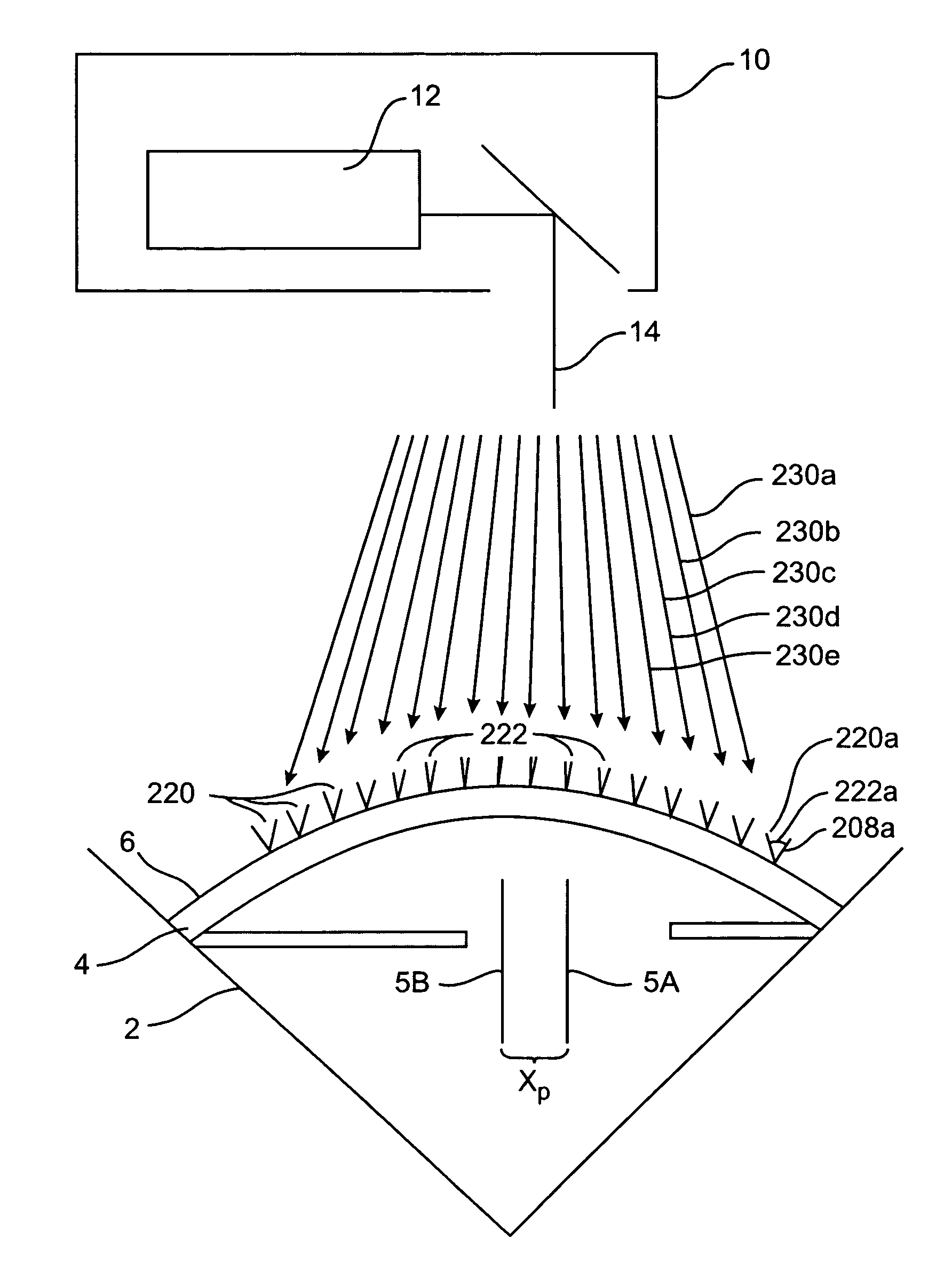
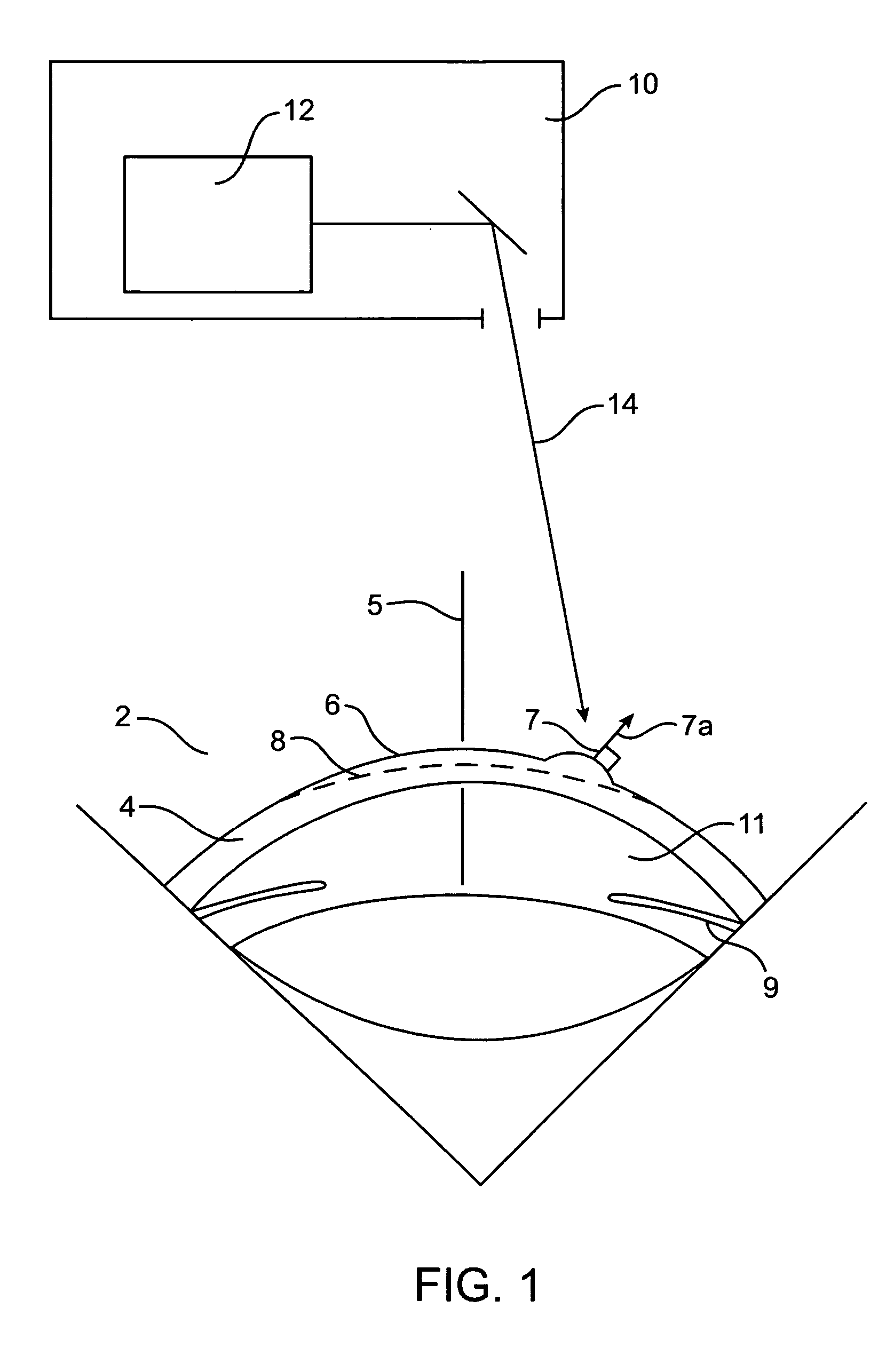
[0015] In specific embodiments, at least one processor determines local ablation properties of a cornea in response to angles between a curved surface and a laser beam. An angle of a laser beam is substantially parallel to an optical axis of an eye. A mapped area includes an apex of a cornea and an apex of a cornea is displaced from a center of a pupil of an eye. A desired shape has a center, and a center of a desired shape is aligned with a center of a pupil of an eye. At least one processor has a computer program including a first virtual shape and a second virtual shape. A first virtual shape represents a depth of material removed from an area to form a desired shape. A second virtual shape is formed from a first virtual shape in response to mapped angles. In an embodiment, a depth of a second virtual shape is greater than a depth of a first virtual shape. In another embodiment, a depth of a second virtual shape is less than a depth of a first virtual shape. A desired shape is based at least in part on a result of a measurement selected from a group consisting of an aberration measurement of an eye, a refractive measurement of the eye, and a topography measurement of an eye.

Problems solved by technology

The known techniques typically do not take into account a detailed ablative interaction of a laser beam with a detailed anatomy of a tissue surface of an eye.

Method used


Image

  • Corneal topography-based target warping system
  • Corneal topography-based target warping system
  • Corneal topography-based target warping system

Examples


Embodiment Construction

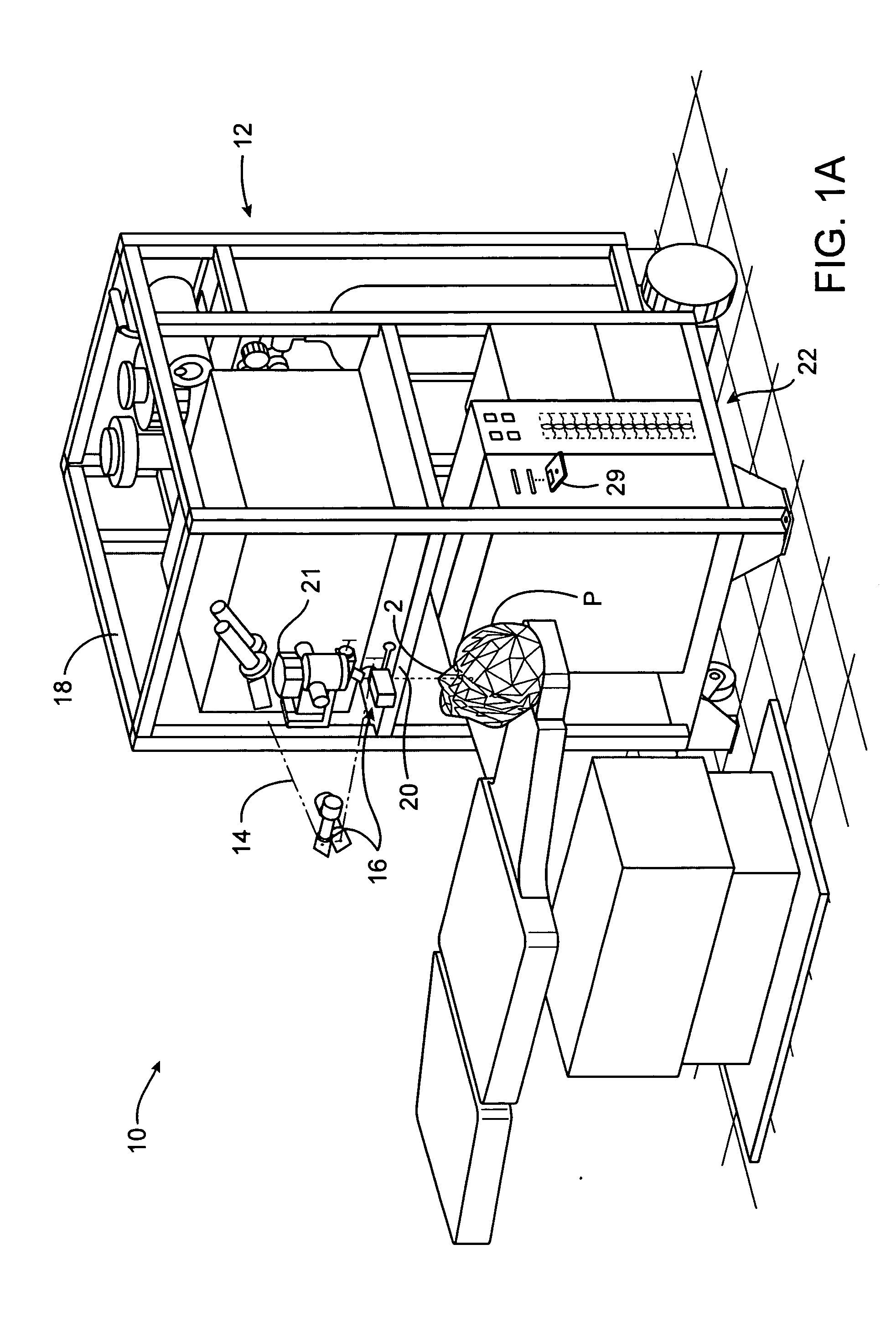
[0037] The present invention is particularly useful for enhancing the accuracy and efficacy of laser eye surgical procedures, such as photorefractive keratectomy (PRK), phototherapeutic keratectomy (PTK), laser assisted in situ keratomileusis (LASIK), laser epithelial keratomileusis (LASEK) and the like. Preferably, the present invention can provide enhanced optical accuracy of refractive procedures by improving a corneal ablation of a refractive treatment program. Hence, while the system and methods of the present invention are described primarily in a context of a laser eye surgery system, it should be understood techniques of the present invention may be adapted for use in alternative eye treatment procedures and systems such as spectacle lenses, intraocular lenses, contact lenses, corneal ring implants, collagenous corneal tissue thermal remodeling, and the like.

[0038] The techniques of the present invention can be readily adapted for use with existing laser systems, wavefront ...


PUM


Abstract

Systems and methods for treating a tissue of an eye with a laser beam include at least one processor that determines angles between a curved surface and a laser beam, controlling an ablative treatment in response to the angles. Angles between a surface of a cornea and a laser beam may be mapped over a treatment area. A mapped area may include an apex of a cornea displaced from a center of a pupil of an eye. Ablation properties may be determined locally in response to the incident angle of a laser beam with respect to a local slope of a tissue surface. The treatment area may be ablated using local ablation properties to form a desired surface shape.

Description

CROSS-REFERENCE TO RELATED APPLICATION [0001] This is a continuation patent application which claims priority from U.S. patent application Ser. No. 10 / 460,060 filed on Jun. 11, 2003, which claims the benefit under 35 USC § 119(e) of U.S. Provisional Patent Application No. 60 / 389,090 filed Jun. 13, 2002, the full disclosure of which is incorporated herein by reference.BACKGROUND OF THE INVENTION [0002] The present invention is generally related to correction of refractive errors and aberrations of the eye. The invention provides devices, systems, and methods for measurement and correction of optical errors of optical systems, and is particularly well suited for correcting refractive optical aberrations of the eye. [0003] Known laser eye surgery procedures generally employ an ultraviolet or infrared laser to remove a microscopic layer of stromal tissue from the cornea of the eye. Examples of laser eye surgery procedures include photorefractive keratectomy (PRK), phototherapeutic kerat...

Claims


Application Information

Patent Timeline
Patent Type & Authority Applications(United States)
IPC IPC(8): A61F9/007A61F9/01
CPCA61B3/107A61F9/008A61F9/00806A61F2009/00882A61F2009/00848A61F2009/00872A61F2009/0088A61F9/00808
Inventor CHERNYAK, DIMITRI
Owner AMO MFG USA INC
Why Eureka
Try Eureka