Control system for internal combustion engine

a control system and internal combustion engine technology, applied in the direction of electric control, ignition automatic control, machines/engines, etc., can solve the problems of increased torque fluctuations, decreased charging efficiency, increased intake air quantity, etc., and achieve the effect of preventing rapid torque fluctuations and further suppressing shocks

Inactive Publication Date: 2005-08-11
TOYOTA JIDOSHA KK
View PDF3 Cites 126 Cited by
  • Summary
  • Abstract
  • Description
  • Claims
  • Application Information

AI Technical Summary

Benefits of technology

[0012] It is therefore an object of the present invention to provide a control system for an internal combustion engine which can prevent torque fluctuations from occurring during a switching between an injector for cylinder-inside injection and an injector for intake port injection to eliminate such conventional problem.
[0016] Further, since over the predetermined period during the switching, at least either one of throttle valve opening angle or ignition timing be changed gradually from an optimum value in the operating condition range using the one of the injectors to an optimum value in the operating condition range using the other one, rapid torque fluctuations are prevented and consequently shocks are further suppressed.

Problems solved by technology

As a result, there occurs an increase in the intake air quantity, thus causing torque fluctuations (increase).
When, on the other hand, the fuel injection is switched from the injector for cylinder-inside injection at a high load to the injector for intake port injection, the charging efficiency decreases, thus causing a change in torque fluctuations (decrease).
However, when the technology described therein is applied to an internal combustion engine which includes an injector for cylinder-inside injection to inject fuel into a cylinder at a high load and an injector for intake port injection to inject fuel into an intake port at low and medium loads, and switches the fuel injection from one of both injectors to the other for use depending on operating conditions, there occurs all the more a problem of producing torque fluctuations at the time of the switching.
As a result, there occurs a change in the intake air quantity, thus causing torque fluctuations.

Method used


Image

  • Control system for internal combustion engine
  • Control system for internal combustion engine
  • Control system for internal combustion engine

Examples


Embodiment Construction

[0022] A preferred embodiment of the present invention will be described below with reference to the drawings.

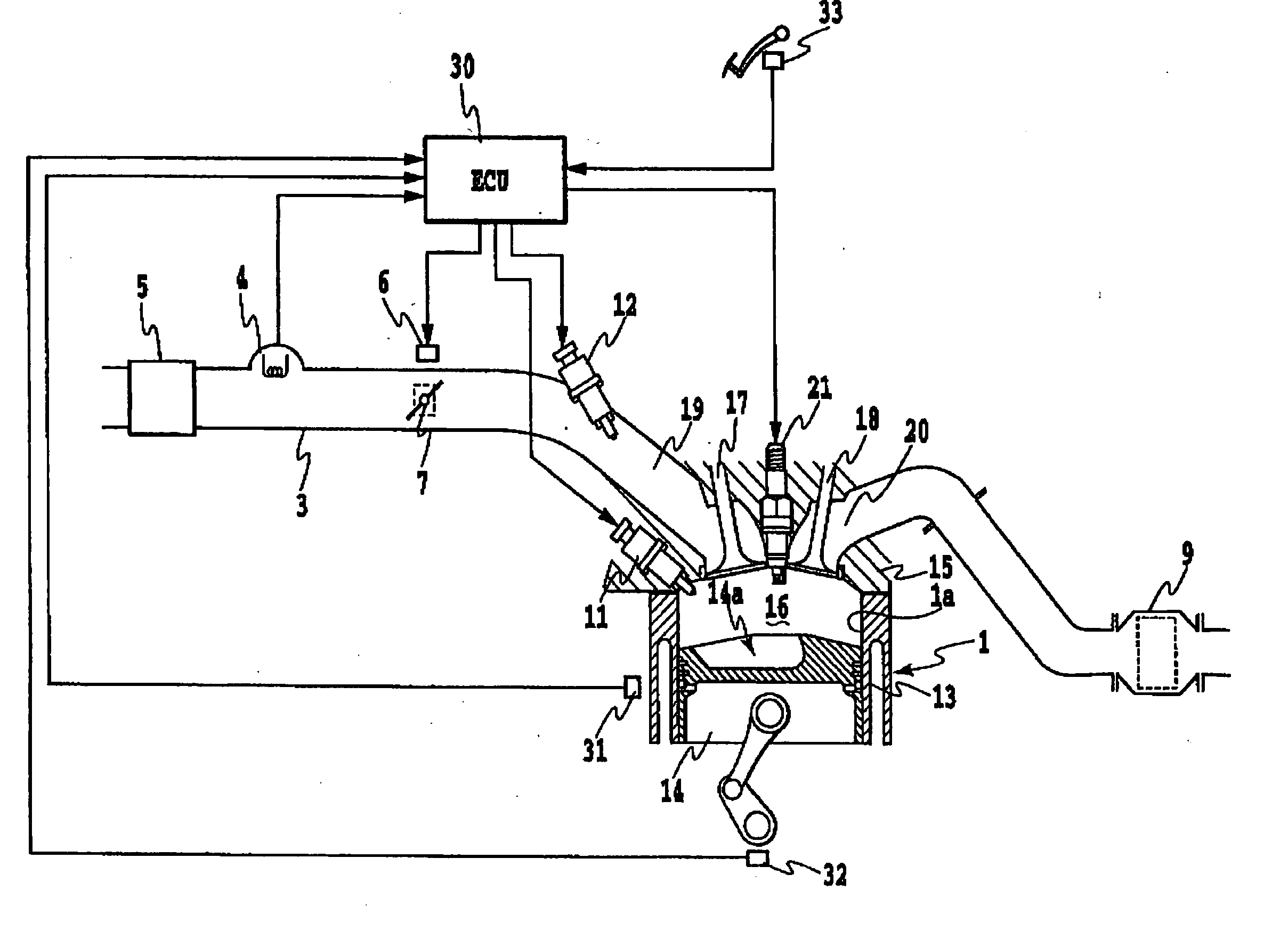
[0023] Referring first to FIG. 1 in which an outline configuration diagram of a control system for an internal combustion engine according to the present invention is shown, the engine 1 includes a plurality of cylinders, for example, four cylinders 1a. Each of the cylinders 1a is connected to an intake duct 3 through each corresponding intake manifold and the intake duct 3 is connected to an air cleaner 5 through an air flow meter 4. A throttle valve 7 actuated by a throttle motor 6 such as a stepping motor is arranged in the intake duct 3. On the other hand, each of the cylinders 1a is coupled to a common exhaust manifold, which is in turn coupled to a three-way catalytic converter 9.

[0024] An injector 11 for cylinder-inside injection to inject fuel into a cylinder and an injector 12 for intake port Injection to inject fuel into an intake port are attached to each of the...


PUM


Abstract

In an internal combustion engine equipped with an injector for oylinder-inside injection to inject fuel into a cylinder and an injector for intake port injection to inject fuel into an intake port, both the injectors being switched for use depending upon operating conditions, wherein when an operating condition range using either one of the first or the second injector is switched to an operating condition range using the other one thereof, the amount of fuel to be injected by the either one of the first or the second injector is gradually decreased and the amount of fuel to be injected by the other one is gradually increased over a predetermined period during the switching. Further, at the time of the switching, at least one of ignition timing and throttle opening angle is gradually varied.

Description

[0001] This application claims priority from Japanese Patent Application No. 2004-032643 filed Feb. 9, 2004, which is incorporated hereinto by reference. BACKGROUND OF THE INVENTION [0002] 1. Field of the Invention [0003] The present invention relates to a control system for an internal combustion engine, and more particularly, to a control system for an internal combustion engine which includes an injector for cylinder-inside injection to inject fuel into a cylinder at a high load and an injector for intake port injection to inject fuel into an intake port at low and medium loads, and which switches the fuel injection from one of the injectors to the other thereof for use depending on operating conditions. [0004] 2. Description of the Related Art [0005] In general, there is known an internal combustion engine that includes an injector for cylinder-inside injection to inject fuel into a cylinder and an injector for intake port injection to inject fuel into an intake port and is adap...

Claims


Application Information

Patent Timeline
Patent Type & Authority Applications(United States)
IPC IPC(8): F02D9/02F02P5/15F02D37/02F02D41/04F02D41/34F02M63/00
CPCF02D37/02F02D41/3094Y02T10/44F02D2041/389F02D2250/21F02D41/34Y02T10/40
Inventor MORI, JUNICHI
Owner TOYOTA JIDOSHA KK
Why Eureka
Try Eureka