Image forming apparatus

a technology of forming apparatus and rgb, which is applied in the direction of visual presentation using printers, instruments, radio frequency controlled devices, etc., can solve the problems of difficult to adjust the rgb to a desired density level and the rgb is not matched, so as to achieve easy adjustment, easy adjustment, and increased exposure amount

Inactive Publication Date: 2005-08-11
KONICA MINOLTA PHOTO IMAGING
View PDF3 Cites 4 Cited by
  • Summary
  • Abstract
  • Description
  • Claims
  • Application Information

AI Technical Summary

Benefits of technology

[0017] According to the present invention, because the light emitting time table is reset based on the detection result of the exposure amount determining section, and the light emitting time of the recording element is adjusted by using the light emitting time table after the reset, even when the exposure amount of the recording head is decreased by the aging deterioration, the exposure amount can be increased, further, can be easily adjusted to a desired density level.
[0018] Further, when the first exposure amount adjusting section

Problems solved by technology

Therefore, as described above, there is a problem that, in the low density portion or high density portion, t

Method used


Image

  • Image forming apparatus
  • Image forming apparatus
  • Image forming apparatus

Examples


first embodiment

The First Embodiment

[0029] Referring to the drawings, the first embodiment of the present invention will be detailed below. However, the scope of the invention is not limited to examples shown in the drawings.

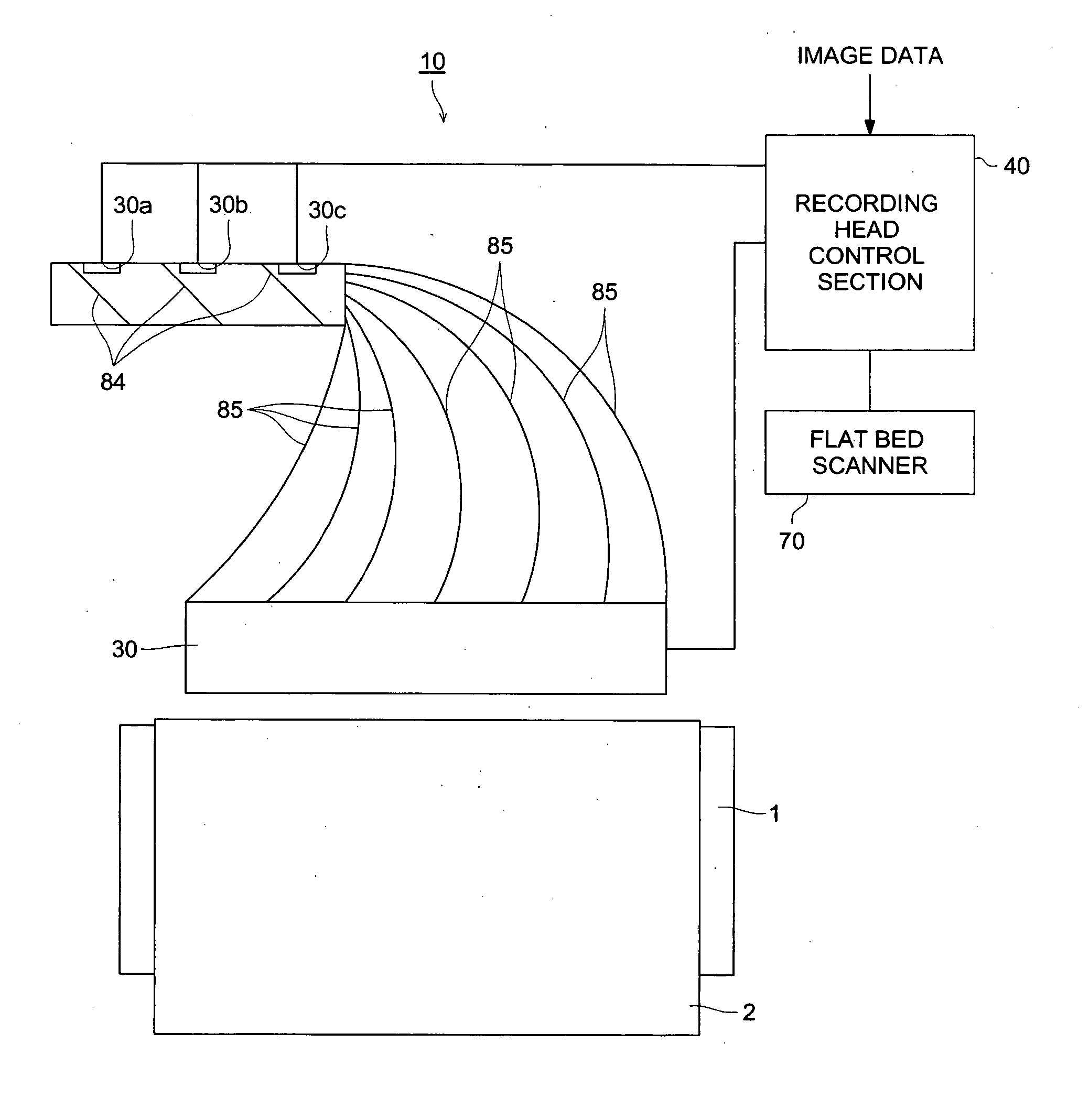
[0030] An outline structure of image forming apparatus 10 of the present invention is shown in FIG. 1. As shown in this figure, image forming apparatus 10 provides with a support drum 1.

[0031] The support drum 1 is rotated by a drive source (not shown), and conveys a color photographic printing sheet (hereinafter, called a printing sheet) 2 fed from a roller (not shown) in an arrow-ed direction. As printing sheet 2, a silver-halide photosensitive material is used.

[0032] Above support drum 1, PLZT type recording head 30 for exposing the printing sheet is provided. LED 30a, 30b, 30c for each color being light sources are connected to recording head 30 through a mirror 84 and an optical fiber 85. A plurality of recording elements (PLZT elements) is array-likely arranged along t...

second embodiment

The Second Embodiment

[0060] Herein, in the first embodiment, a case where the exposure amount value to be adjusted by first exposure amount adjusting section 41 is calculated based on EST is described. In the second embodiment, a case where it is selectively used based on EST from a plurality of current values set stepwise, will be described. Hereupon, in the following description, for the same part as in the first embodiment, the same sign is affixed, and its description will be omitted.

[0061] As in this second embodiment, when a current value is selected and used based on EST from a plurality of current values set stepwise, the difference of EST is set for each stage, and this difference is the judgment reference of the judgment section 43. This difference of EST is called an exposure amount adjustment operation range which is a judgment reference whether an exposure amount adjustment is conducted by the first exposure amount adjusting section 41. For example, as shown in FIG. 7,...


PUM


Abstract

An image forming apparatus comprises a recording head for exposing a printing sheet by emitting lights under a condition that an exposure amount of the lights for each pixel is independently controlled and adjusted, an exposure amount determining section for determining whether the exposure amount is within a predetermined range, and a first exposure amount adjusting section for adjusting the exposure amount based on a light emitting time of the lights table including a relationship between a light emitting time and the density of an image, wherein the first exposure amount adjusting section resets the light emitting time table based on a determination of the exposure amount determining section.

Description

FIELD OF THE INVENTION [0001] The present invention relates to an image forming apparatus, particularly, to an image forming apparatus by which an image is formed while the density level is output-adjusted. BACKGROUND OF THE INVENTION [0002] Conventionally, in an image forming apparatus for forming an image on a printing sheet by conducting digital exposure, there is provided a recording head for exposing a printing sheet after adjusting an exposure of each pixel for the image by emitting light under the condition each pixel is independently driven and controlled. In this exposure amount adjustment, used is a method by which the voltage or current of the recording head is varied and adjusted (for example, refer to the Patent Document 1), or a method by which the image data is converted by an output conversion LUT (Look Up Table) and adjusted (for example, refer to the Patent Document 2). [0003] (Patent Document 1) Japanese Patent Application Open to Public: PaTokkai No. 2000-356830 ...

Claims


Application Information

Patent Timeline
IPC IPC(8): G06K15/12B41J2/445H01L27/00H01L27/148H04N1/40H04N1/407
CPCG06K15/1209H01L27/14806H04N1/4076H04N1/40031H04N1/40006
Inventor DEGUCHI, TAKASHISUZUKI, ATSUSHINAKAHANADA, MANABUSAITO, TAKESHI
Owner KONICA MINOLTA PHOTO IMAGING
Why Eureka
Try Eureka