Dual airbag airspring

a technology of air springs and airbags, applied in the field of air springs, can solve the problems of difficulty in packaging of auxiliary air tanks, and achieve the effect of rapid pressure and volume chang

Active Publication Date: 2005-08-11
ARVINMERITOR TECH
View PDF17 Cites 75 Cited by
  • Summary
  • Abstract
  • Description
  • Claims
  • Application Information

AI Technical Summary

Benefits of technology

[0005] The air spring assembly according to the present invention provides a primary airbag mounted around a piston airbag such that the piston airbag provides a rolling surface for the primary airbag. A change in the piston airbag volume changes the effective piston area of the primary airbag. A relatively small change in the effective piston area provides a chang

Problems solved by technology

Disadvantageously, the auxiliary air tanks may present packaging difficulties and are limited

Method used


Image

  • Dual airbag airspring
  • Dual airbag airspring
  • Dual airbag airspring

Examples


Embodiment Construction

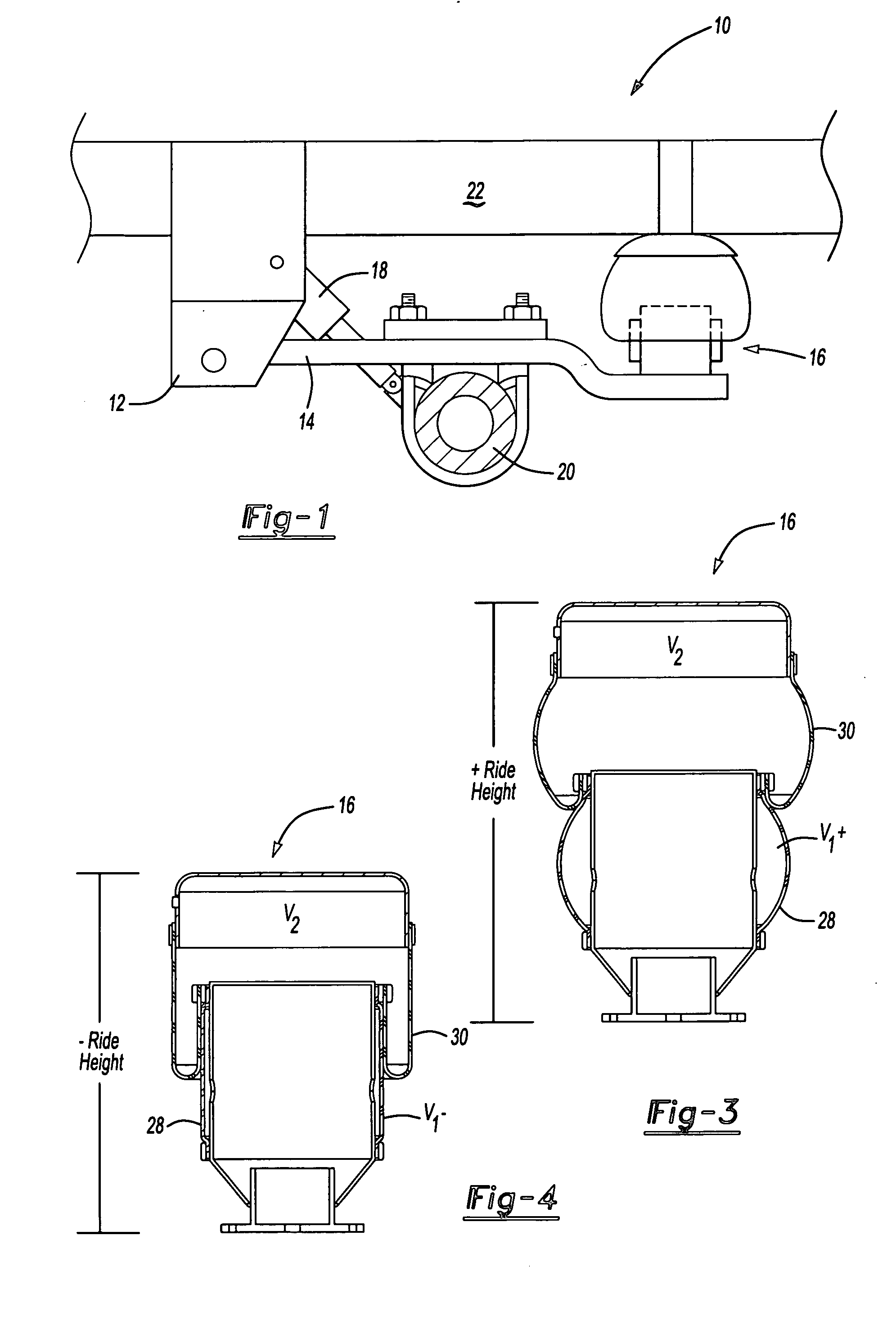
[0012]FIG. 1 illustrates an air suspension system 10 for a vehicle. The system 10 generally includes a bracket 12, a longitudinal member 14, an air spring assembly 16, a damper 18 and an axle assembly 20. The system is fixed to a chassis of the vehicle (shown schematically at 22). It should be understood that although a particular component arrangement is disclosed in the illustrated embodiment, other arrangements will benefit from the instant invention.

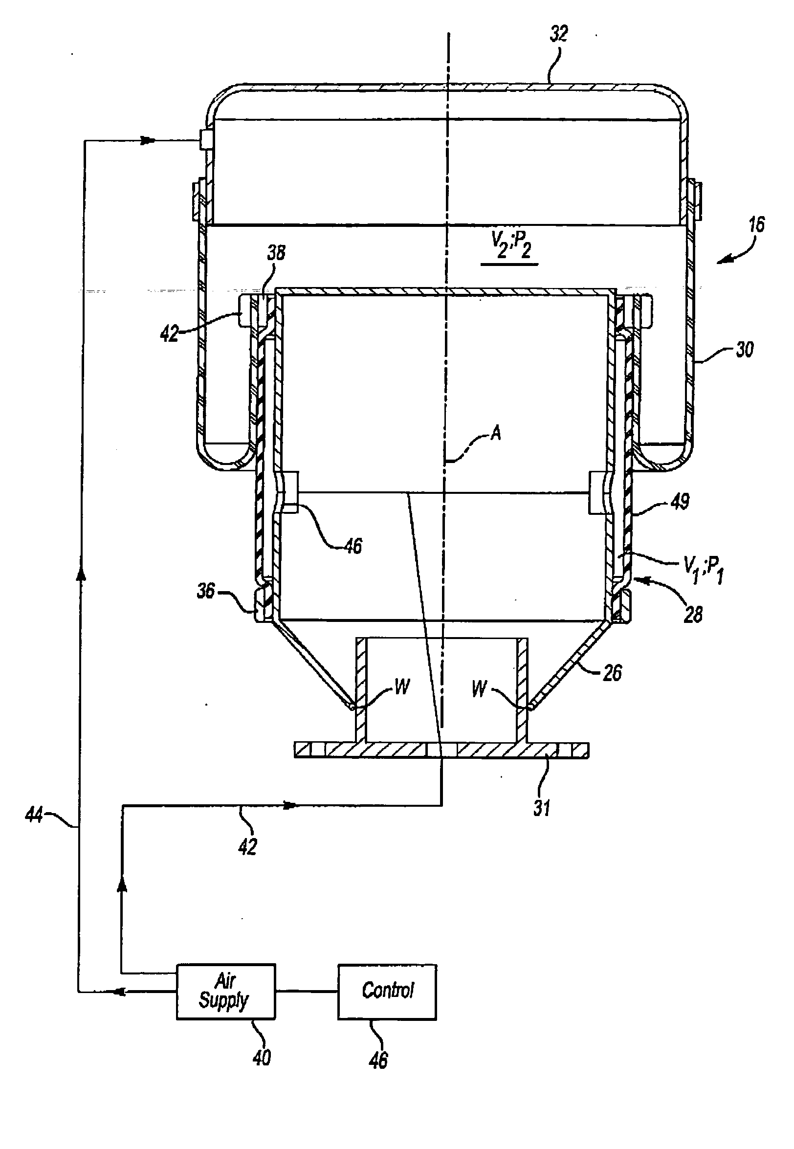
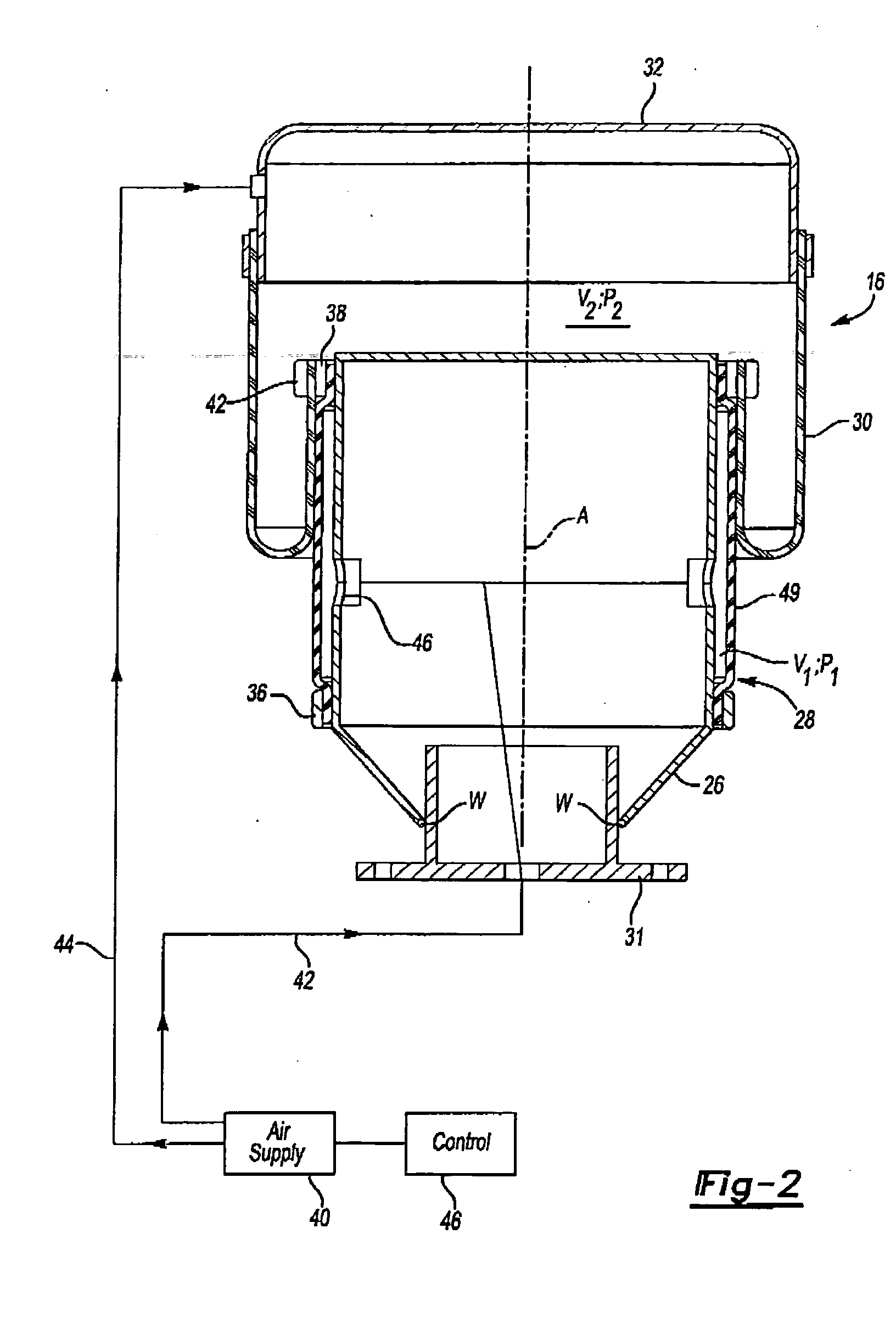
[0013] Referring to FIG. 2, the air spring assembly 16 is illustrated in cross-section. The air spring assembly 16 is defined along an axis A and includes a piston support 26, a piston airbag 28 and a primary airbag 30. An upper mount 32 attached to the primary airbag 30 and a lower mount 31 (illustrated schematically) preferably provide attachment for the air spring assembly 16.

[0014] The piston support 26 is preferably a cylindrical member defined about the axis A. The outer piston 26 is preferably attached to the lower mount 31 ...


PUM


Abstract

An air spring assembly includes a primary airbag mounted to a piston air bag such that the piston airbag provides a rolling surface for the primary airbag. A change in the piston airbag pressure changes the effective rate of the primary air spring. A relatively small change in the piston airbag volume provides a change in the spring rate of air spring assembly as the diameter of the rolloff surface is selectively modified.

Description

BACKGROUND OF THE INVENTION [0001] The present invention relates to an air spring, and more particularly to an air spring with an inner airbag as a roll off piston. [0002] Air spring assemblies are utilized for a variety of applications. One such application is to cushion the ride of a vehicle. An air spring assembly generally includes a flexible member attached to a piston. The piston advances or retreats into the interior of the flexible member, which changes the internal volume of the assembly. The spring rate depends on the change of internal volume and the effective area of the piston. In addition, the amount of air delivered to the interior of the flexible member is adjustable to vary the preload or ride height. [0003] To vary the spring rate of a conventional air spring, auxiliary air tanks are selectively connected to the flexible member to change the effective volume of the air spring. Disadvantageously, the auxiliary air tanks may present packaging difficulties and are lim...

Claims


Application Information

Patent Timeline
IPC IPC(8): B60G11/28B60G17/048B60G17/052F16F9/04F16F9/05
CPCB60G11/28B60G17/0485B60G17/0521F16F9/057B60G2202/412B60G2500/20F16F9/049B60G2202/152
Inventor LLOYD, JEFFREY
Owner ARVINMERITOR TECH
Why Eureka
Try Eureka