Linear motor
a linear motor and motor body technology, applied in the field of linear motors, can solve the problems of increasing sacrificing motor performance, and difficult selection of insulation materials, and achieve the effects of improving thrust characteristics, reducing material cost and manufacturing steps, and improving mechanical dimensions
- Summary
- Abstract
- Description
- Claims
- Application Information
AI Technical Summary
Benefits of technology
Problems solved by technology
Method used
Image
Examples
embodiment 1
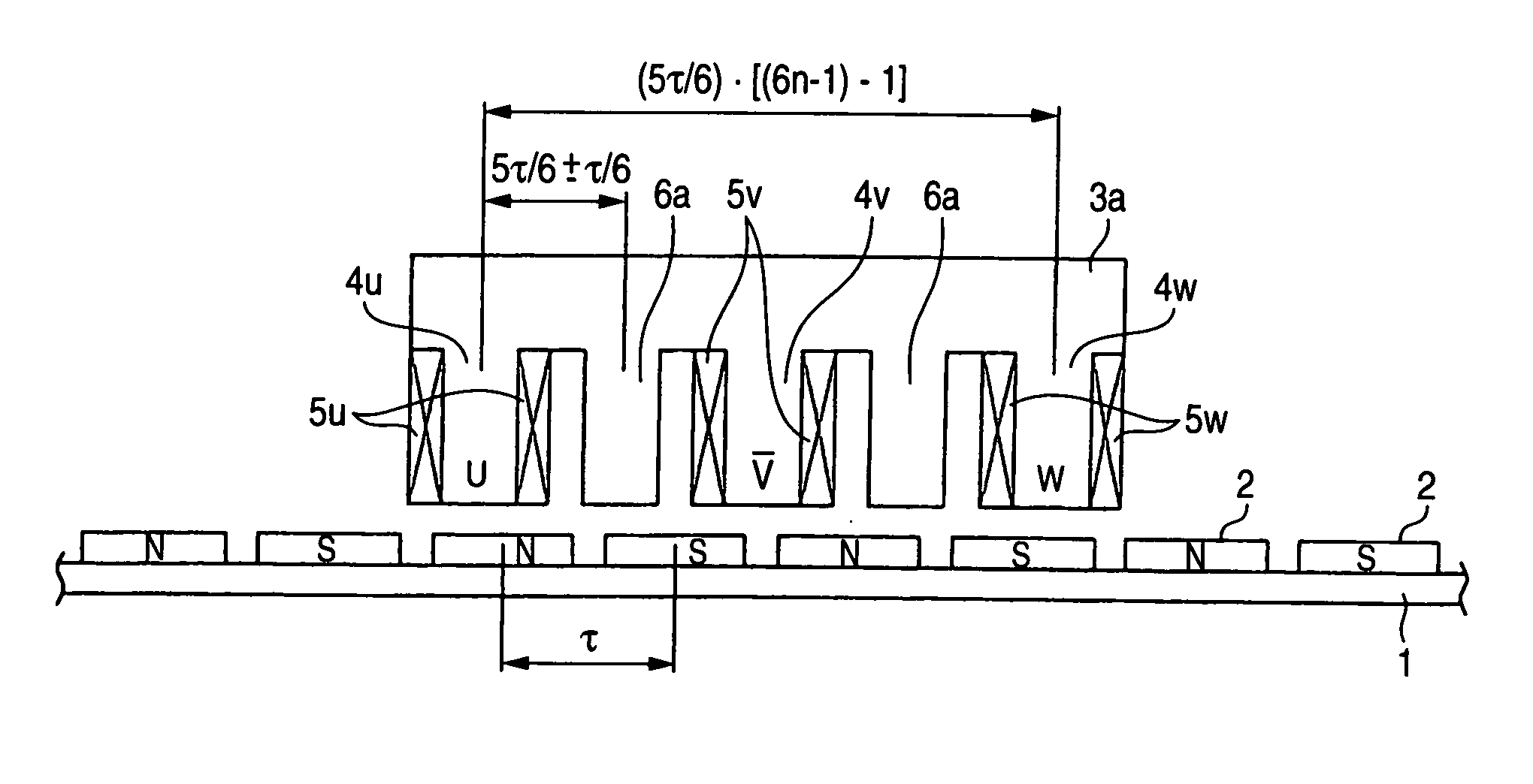
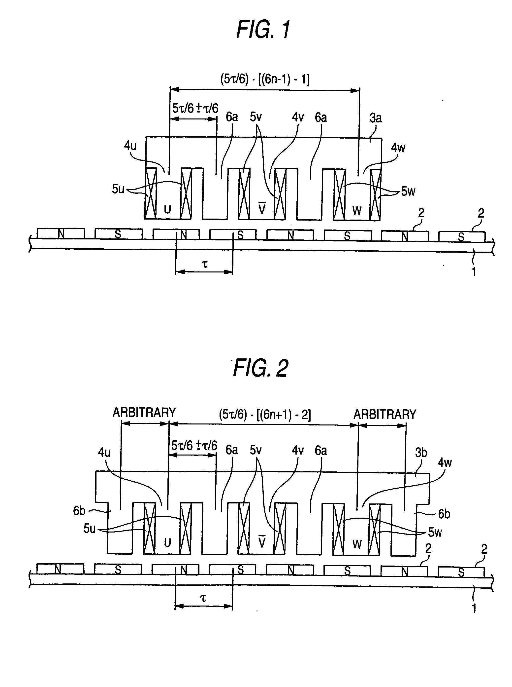
[0024] Referring to FIG. 1, the structure of a linear motor according to an embodiment 1 of this invention will be described below. FIG. 1 shows a moving coil type linear motor, in which the field permanent magnets 2 are arranged at an equal pitch around a field iron core 1 on the stator (field magnetic pole) side so that the poles are alternately changed. Also, an armature 3a on the needle side is arranged oppositely via a magnetic gap on a magnetic pole face of the field permanent magnets 2 provided on the stator side. The armature 3a consists of an armature core forming the teeth and a yoke portion by punching an electromagnetic steel plate like the comb teeth, coil being wound around a plurality of teeth 4u, 4v and 4w of this armature core to form the armature windings 5u, 5v and 5w.
[0025] In FIG. 1, coil is wound around the teeth 4u, 4v and 4w of the armature 3a to form the armature windings 5u, 5v and 5w. The teeth 6a without coil winding is disposed between teeth 4u and 4v a...
embodiment 2
[0031] Referring to FIG. 2, the structure of a linear motor according to an embodiment 2 of this invention will be described below. In FIG. 2, the parts with reference numerals 1, 2, 4u, 4v, 4w, 5u, 5v, 5w and 6a are the same as in FIG. 1, and are not described here.
[0032] Coil is wound around the teeth 4u, 4v and 4w of an armature 3b to form the armature windings 5u, 5v and 5w. Also, the teeth 6a has no coil winding. The teeth with coil winding 4u, 4v and 4w and the teeth 6a without coil winding are alternately arranged Also, the teeth 6b without coil winding are formed on both sides of the armature 3b, and has an arbitrary shape and pitch.
[0033] The linear motor according to the embodiment 2 has a combination of the number of magnetic poles in the field magnetic poles with permanent magnets and the number of teeth for the armature as 5n to 6n+1 (n: natural number that is a factor for deciding the number of teeth). The interval between teeth for the armature except for the teeth ...
embodiment 3
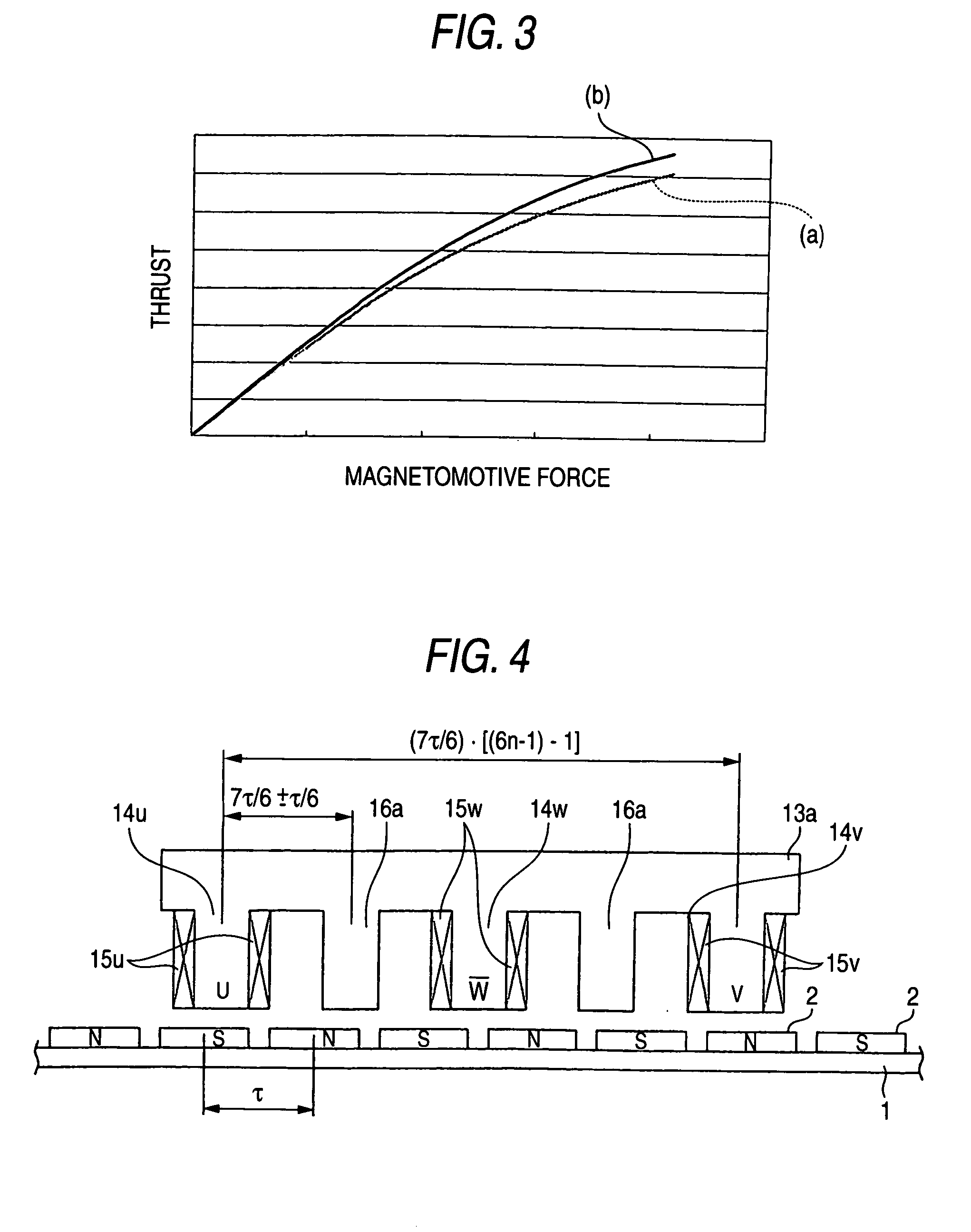
[0039] Referring to FIG. 4, the structure of a linear motor according to an embodiment 3 of this invention will be described below. In FIG. 4, the parts with reference numerals 1 and 2 are the same as in FIG. 1, and not described here. An armature 13a on the needle side is arranged oppositely via a magnetic gap on a magnetic pole face of the field permanent magnets 2 provided on the stator side. The armature 13a consists of an armature core forming the teeth and a yoke portion by punching an electromagnetic steel plate like the comb teeth, coil being wound around a plurality of teeth 14u, 14v and 14w for this armature core to form the armature windings 15u, 15v and 15w.
[0040] In FIG. 4, coil is wound around the teeth 14u, 14w and 14v of the armature 13a to form the armature windings 15u, 15w and 15v. The teeth 16a without coil winding is disposed between teeth 14u and 14w and between teeth 14w and 14v. The teeth 14u, 14w and 14v with coil winding and the teeth 16a without coil wind...
PUM
 Abstract
Description
Claims
Application Information
 - R&D
- Intellectual Property
- Life Sciences
- Materials
- Tech Scout
- Unparalleled Data Quality
- Higher Quality Content
- 60% Fewer Hallucinations
Browse by: Latest US Patents, China's latest patents, Technical Efficacy Thesaurus, Application Domain, Technology Topic, Popular Technical Reports.
© 2025 PatSnap. All rights reserved.Legal|Privacy policy|Modern Slavery Act Transparency Statement|Sitemap|About US| Contact US: help@patsnap.com


