Laser marking method

Inactive Publication Date: 2005-08-11
FUJIFILM CORP
View PDF10 Cites 3 Cited by
  • Summary
  • Abstract
  • Description
  • Claims
  • Application Information

AI Technical Summary

Benefits of technology

[0029] Another object of the present invention is to provide a laser marking method which, regardless of changes in output of a laser oscillator such as a laser oscillating tube or the like, can form, on a photosensitive material, a marking pattern formed of dots or an arrangement of dots which are high-quality and have good visibility.
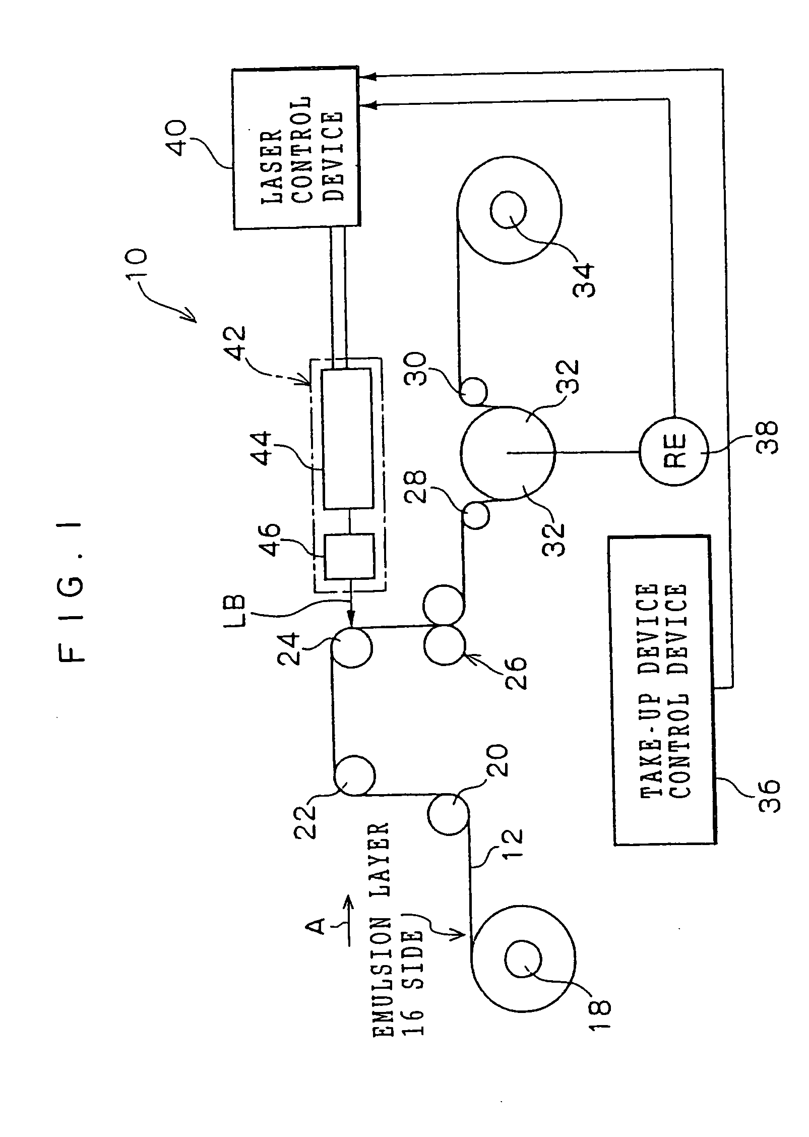
[0051] In this way, if the interruption is short, by starting conveying of the photosensitive material, marking onto the photosensitive material is possible. Therefore, the production efficiency can be prevented from deteriorating.

Problems solved by technology

It is difficult to form dots which have sufficient visibility.
However, the existence of a pigment or a dye at the surface of the photosensitive material may affect the image formed on the photosensitive material.
Further, in order to avoid such effects, further cost and efforts are required.
When forming a character by a dot arrangement or a marking pattern in which a plurality of characters are consecutively recorded by such a laser oscillating tube, the visibility of the dots or the characters formed by dot arrangements, which are formed immediately after marking begins, is extremely poor.
However, during the time of driving by each pulse, a variation in output occurs such that the output is highest immediately after the start of driving, and then the output suddenly falls.

Method used


Image

  • Laser marking method
  • Laser marking method
  • Laser marking method

Examples


experimental examples

[0135] Shown here are experimental results of evaluating the visibility of the dot 16A at the time when energy required for forming a proper dot was applied by controlling the illumination time of the laser beam LB by using laser oscillators of different outputs.

[0136]FIG. 6 shows the basic structure of a testing device 50 which carries out marking by using the laser oscillator 44 which oscillates a CO2 laser.

[0137] In this experiment, because it is not necessary to scan the laser beam LB, at the testing device 50, a collective lens 54 is disposed at the emitting end of the laser oscillator 44 which is driven by the laser control device 40. The laser beam LB is illuminated toward a sample 56 of the X-ray film 12. Note that, in the testing device 50, the beam diameter of the laser beam LB emitted from the laser oscillator 44 is about 4 mm. The collective lens 54 collects the laser beam LB such that the laser beam LB is illuminated in the form of a spot having a spot diameter of abo...


PUM

PropertyMeasurementUnit
Photosensitivityaaaaaaaaaa

Abstract

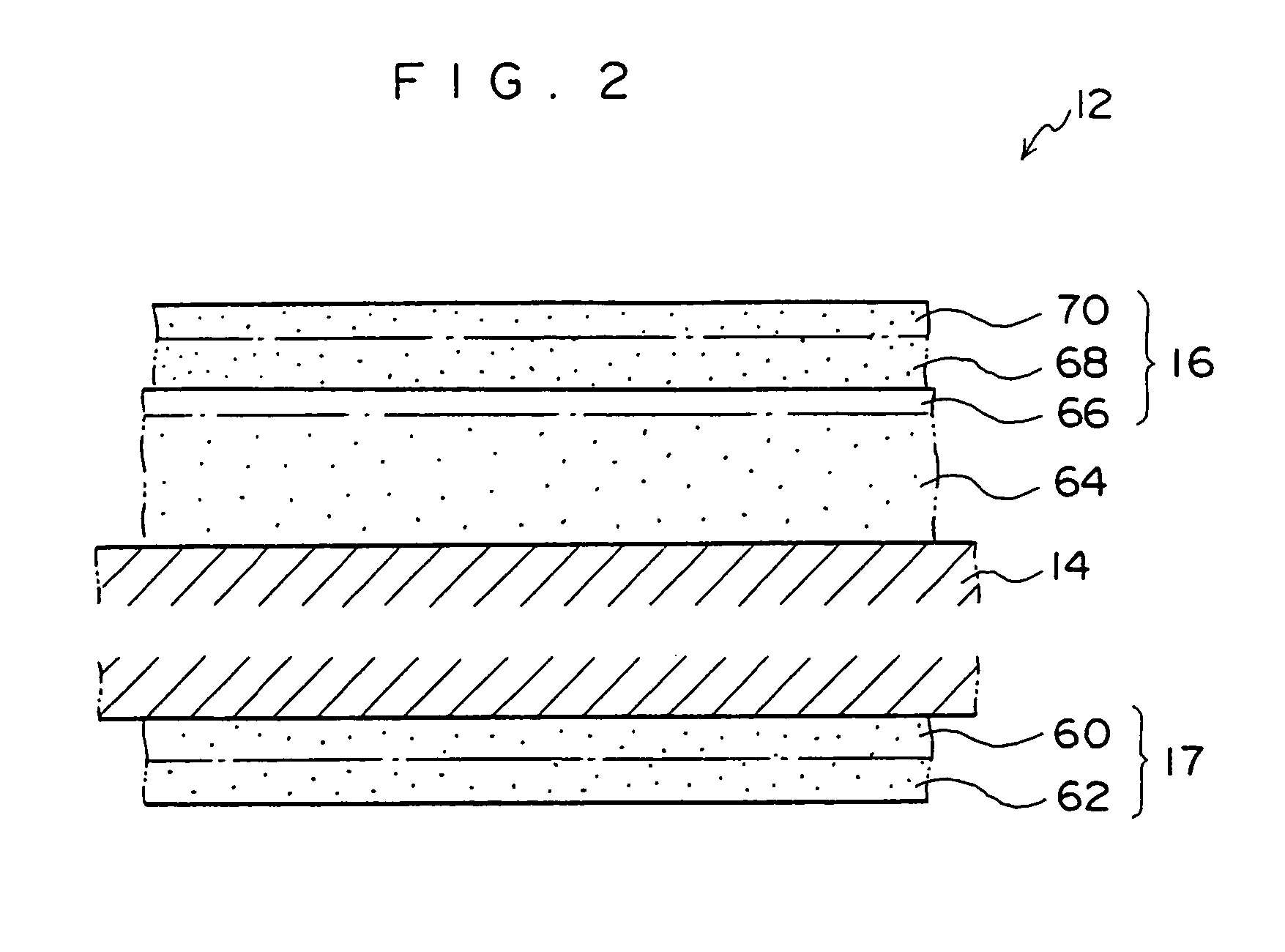
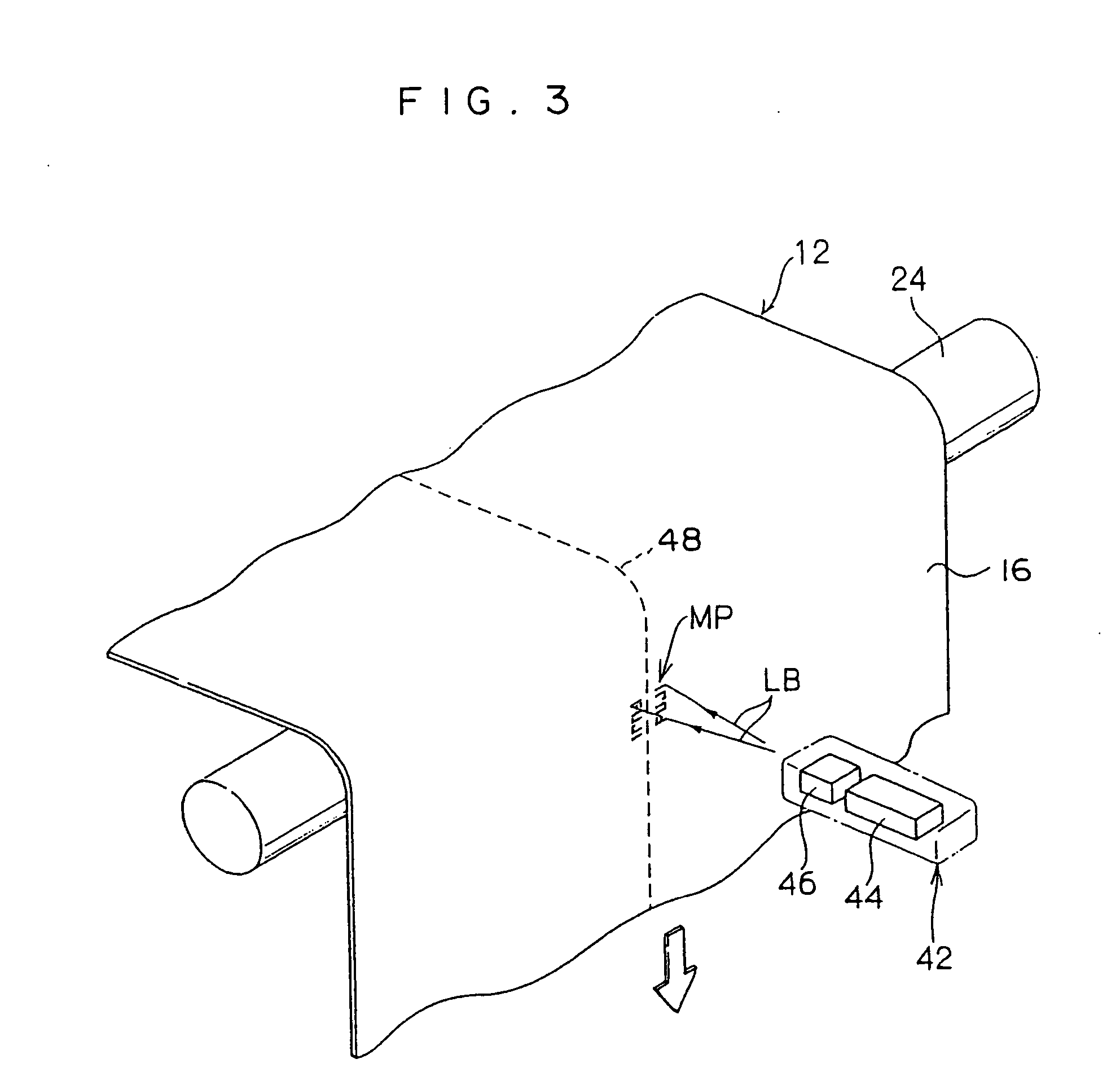
In a marking device, by illuminating a laser beam onto an X-ray film which is a light-photosensitive heat-developing photosensitive material, an inner portion of a surface layer is melted, a cavity is formed, and a dot, which projects a surface out in a convex shape, is formed. At this time, an illumination time of the laser beam is controlled in order to control melting of the surface layer. In the marking device, when conveying of an X-ray film is stopped, oscillation of a laser oscillating tube is continued until a predetermined period of time elapses. When stoppage is for a short time, control is carried out such that marking can be started quickly.

Description

CROSS-REFERENCE TO RELATED APPLICATION [0001] This application claims priority under 35 USC 119 from Japanese Patent Applications No. 2002-312293 and No. 2002-376855, the disclosures of which are incorporated by reference herein. BACKGROUND OF THE INVENTION [0002] 1. Technical Field [0003] The present invention relates to a laser marking method which forms characters or symbols by dots or an arrangement of dots formed by illuminating a laser beam, on a photosensitive material in which a surface layer including an emulsion layer is formed on the surface of a base layer. More specifically, the present invention relates to a laser marking method which forms a marking pattern such as, for example, characters or symbols, by illuminating a laser beam onto a photosensitive material which may be a light-photosensitive heat-developing photosensitive material. [0004] 2. Description of the Related Art [0005] In medical fields in recent years, a reduction in waste solutions from processing aris...

Claims


Application Information

Patent Timeline
IPC IPC(8): B23K26/073B41J2/44B41M5/26G03C1/498G03C5/16
CPCB23K26/0734B41J2/442G03C1/4989G03C5/16G03C2005/168
Inventor ENDO, KEISUKENISHIDA, HIROYUKI
Owner FUJIFILM CORP
Why Eureka
Try Eureka