Communication terminal device and base station device
Inactive Publication Date: 2005-08-11
PANASONIC CORP
View PDF8 Cites 52 Cited by
Summary
Abstract
Description
Claims
Application Information
AI Technical Summary
This helps you quickly interpret patents by identifying the three key elements:
Problems solved by technology
Method used
Benefits of technology
Benefits of technology
[0006] The object is achieved by configuring a communication terminal apparatus such that when transmission data is accumulated in a buffer, CQI is transmitted and when no transmission data is in the buffer, CQI is not transmitted. Further, when the amount of transmission data accumulated in the buffer is at or above a threshold value so that the transmission data is likely to overflow, or when a small amount of accumulated transmission data is left in the buffer so that the transmission thereof is desirably finished early, the communication terminal apparatus increases the number of transmit slots temporarily and the base station apparatus performs scheduling that preferentially assigns transmission to a communication terminal apparatus from which the number of CQI receive slots in a time unit of CQI transmit assignment has increased, thereby achieving the object. Yet further, when tolerable delay time of transmission data accumulated in the buffer is of a small amount, the communication terminal apparatus increases the number of transmit slots temporarily and the base station apparatus performs scheduling such that a communication terminal apparatus from which the number of CQI receive slots in a time unit of CQI transmit assignment has increased can transmit at high priority, thereby achieving the object.
Problems solved by technology
However, for conventional communication terminal apparatuses and base station apparatus, large volumes of data are transmitted at high speed from the base station apparatus to the communication terminal apparatuses using a system exclusively for the downlink like the HSDPA system, and when applying this system to the uplink as it is, the problem occurs that optimum scheduling according to data cannot be performed in the base station apparatus.
Method used
Image
Click on the blue label to locate the original text in one second.
Reading with bidirectional positioning of images and text.
Examples
embodiment 1
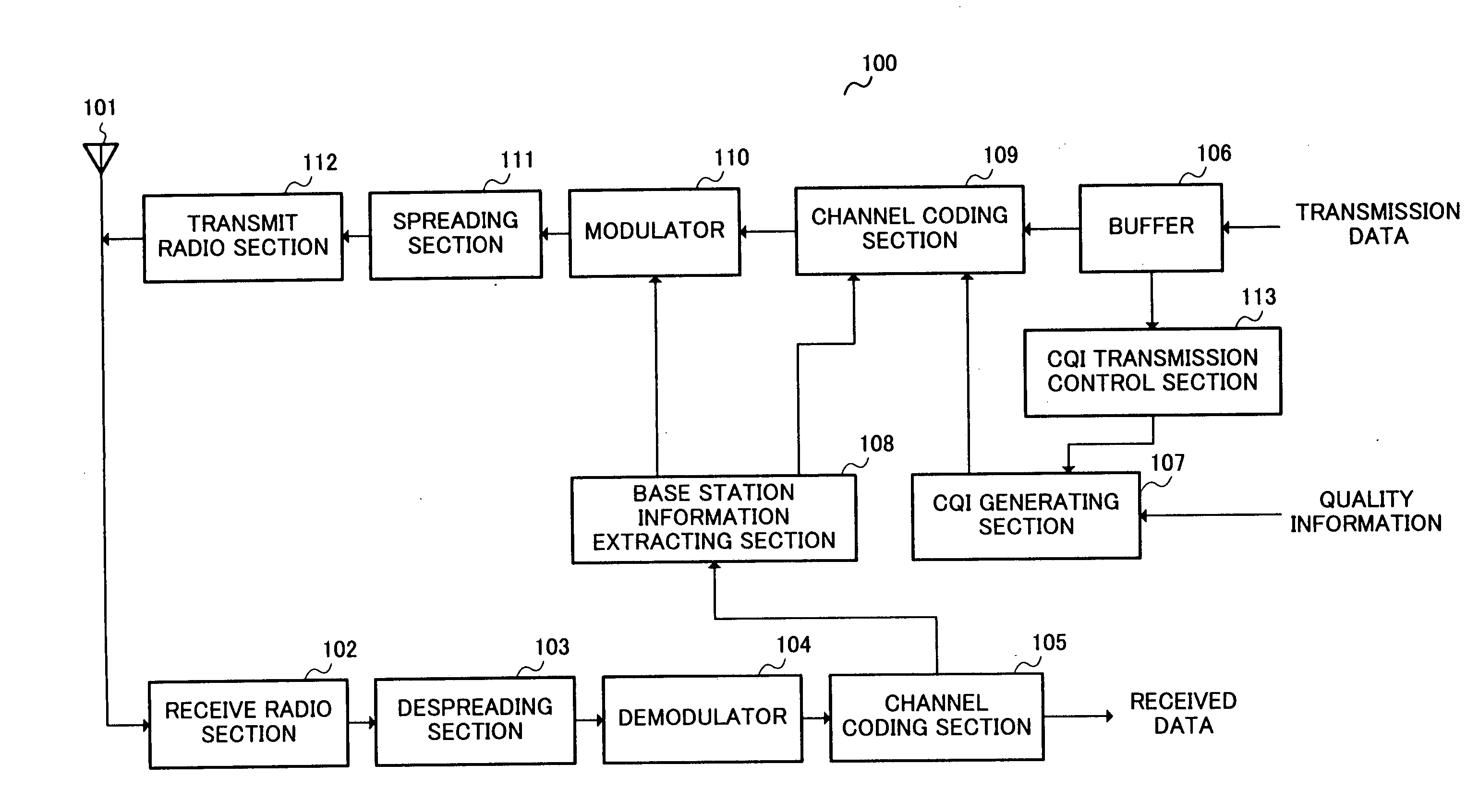
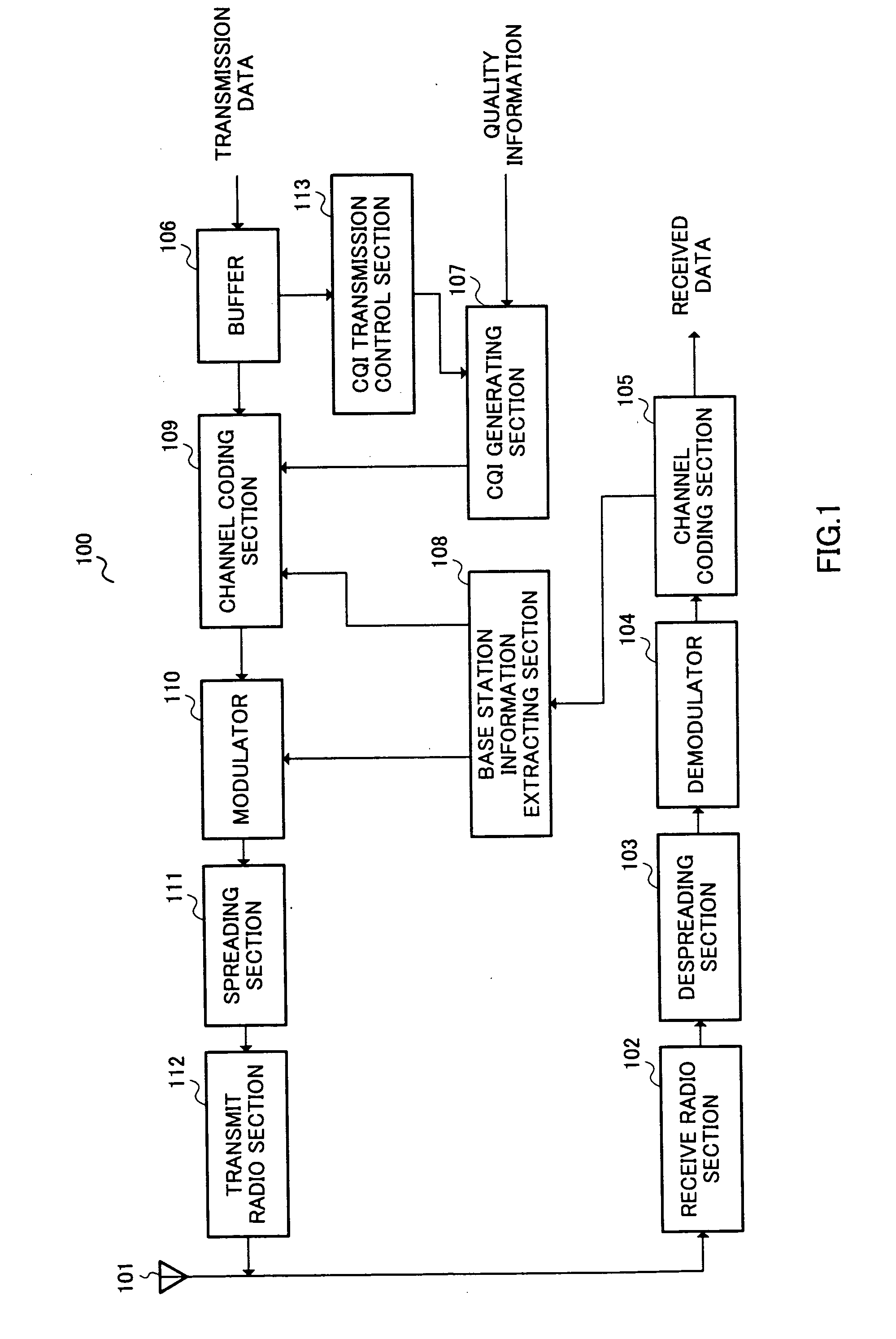
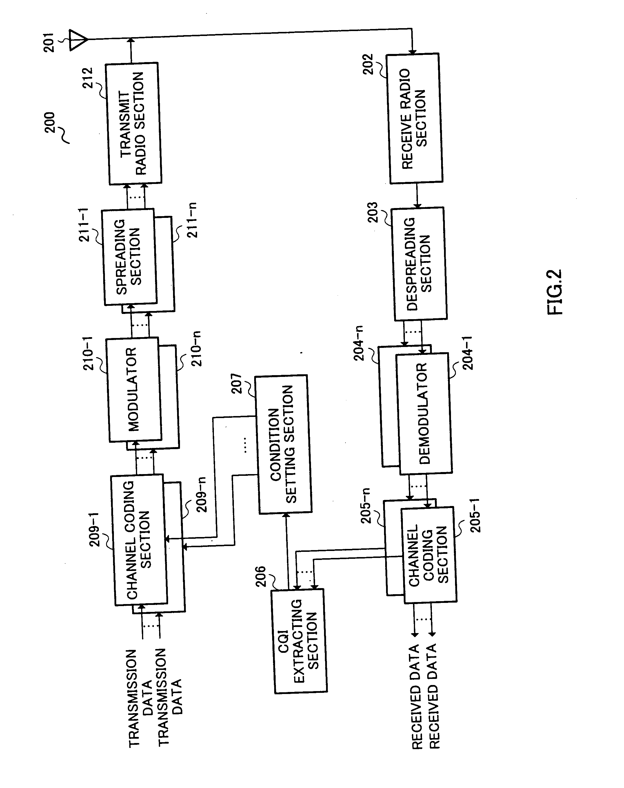
[0032]FIG. 1 is a diagram showing the configuration of a mobile apparatus 100, a communication terminal apparatus, according to the present embodiment, and FIG. 2 is a diagram showing the configuration of a base station apparatus 200.
[0033] Mobile apparatus 100 comprises essentially an antenna 101, a receive radio section 102, a despreading section 103, a demodulator 104, a channel coding section 105, a buffer 106, a CQI generating section 107, a base station information extracting section 108, a channel coding section 109, a modulator 110, a spreading section 111, and a transmit radio section 112.
[0034] Base station apparatus 200 comprises essentially an antenna 201, a receive radio section 202, a despreading section 203, demodulators 204-1 to 204-n, channel coding sections 205-1 to 205-n, a CQI extracting section 206, a condition setting section 207, channel coding sections 209-1 to 209-n, modulators 210-1 to 210-n, spreading sections 211-1 to 211-n, and a transmit radio section...
embodiment 2
[0060]FIG. 4 is a diagram showing the configuration of a base station apparatus 400 according to the present embodiment, and FIG. 5 is a diagram showing the configuration of a condition setting section 402. The present embodiment is characterized in that the number of transmit slots for CQI is increased and decreased according to the amount of data accumulated in the buffer in mobile apparatus 100. In the present embodiment, the configuration of FIG. 4 differs from that of FIG. 2 in that a report timing observing section 401 is provided. Because the configuration of the mobile apparatus is the same as in FIG. 1, a description thereof is omitted. Moreover, in FIG. 4, the same constituents as in FIG. 2 are indicated by the same reference numerals and a description thereof is omitted.
[0061] CQI transmission control section 113 of mobile apparatus 100 compares the cumulative amount of transmission data accumulated in buffer 106 with a threshold value, which amount is input from the buf...
embodiment 3
[0078]FIG. 10 is a diagram showing the configuration of a mobile apparatus 1000 according to the present embodiment. The present embodiment is characterized in that the number of CQI transmit slots in a time unit of CQI transmit assignment is changed according to tolerable delay time. In the present embodiment, the configuration of FIG. 10 differs from that of FIG. 1 in that a tolerable delaytime information generating section 1001 is provided. Note that the same constituents as in FIG. 1 are indicated by the same reference numerals and a description thereof is omitted. Also, because the configuration of the base station apparatus is the same as in FIG. 4, a description thereof is omitted.
[0079] First, the configuration of mobile apparatus 1000 will be explained using FIG. 10. CQI transmission control section 113 compares tolerable delay time information inputted from tolerable delay time information generating section 1001 with a threshold value, and when the tolerable delay time...
PUM
Abstract
A buffer 106 stores transmission data temporarily. A CQI transmission control section 113 outputs an instruction signal for generating CQI to a CQI generating section 107 when transmission data is accumulated in buffer 106. CQI generating section 107 generates CQI based on quality information when the instruction signal is input from CQI transmission control section 113, and does not generate CQI when the instruction signal is not input from CQI transmission control section 113. A base station information extracting section 108 extracts transmit parameter information and scheduling information included in received data. A channel coding section 109 encodes transmission data based on encoding rate information in the transmit parameter information. A modulator 110 modulates the transmission data based on modulation scheme information in the transmit parameter information. By this means, a large volume of packet data can be communicated at high speed on the uplink in optimum conditions according to communication environment.
Description
TECHNICAL FIELD [0001] The present invention relates to a communication terminal apparatus and a base station apparatus, and particularly to a communication terminal apparatus and a base station apparatus in a system that performs high speed packet transmission on the uplink, wherein scheduling is performed by the base station apparatus based on CQI transmitted from the communication terminal apparatus. BACKGROUND ART [0002] To date, in the field of radio communication systems, HSDPA (High Speed Downlink Packet Access) has been standardized where a plurality of communication terminal apparatuses share a downlink channel of high speed and large capacity and high speed packet transmission is performed on the downlink. [0003] In this HSDPA system, a base station apparatus has communication terminal apparatuses transmit a signal indicating the modulation scheme and encoding rate of packet data that can be demodulated in the communication terminal apparatus and being called CQI (Channel ...
Claims
Application Information
Patent Timeline
Application Date:The date an application was filed.
Publication Date:The date a patent or application was officially published.
First Publication Date:The earliest publication date of a patent with the same application number.
Issue Date:Publication date of the patent grant document.
PCT Entry Date:The Entry date of PCT National Phase.
Estimated Expiry Date:The statutory expiry date of a patent right according to the Patent Law, and it is the longest term of protection that the patent right can achieve without the termination of the patent right due to other reasons(Term extension factor has been taken into account ).
Invalid Date:Actual expiry date is based on effective date or publication date of legal transaction data of invalid patent.

