
Device and method for measuring temperature in molten metals

a technology of molten metals and optical fibers, applied in the direction of heat measurement, optical radiation measurement, instruments, etc., can solve the problem that the cladding cannot provide the optimum protection of the optical fiber, and achieve the effect of improving the general functionality of the device, improving the control of consumption, and reducing the functionality

Active Publication Date: 2005-08-11
HERALUS ELECTRO NITE INT NV
View PDF12 Cites 27 Cited by
  • Summary
  • Abstract
  • Description
  • Claims
  • Application Information

AI Technical Summary

Benefits of technology

[0008] It is expedient if the fiber is surrounded directly by a metal tube, particularly by a steel tube. Furthermore, it can be advantageous if the optical fiber is connected directly to a detector, wherein the detector can be arranged in the consumable body.
[0010] In particular, it is advantageous if the optical fiber is formed as a continuous fiber and further if it can be movably arranged within the carrier and / or the consumable body. Consumed parts of the fiber can then be replaced simply by continuously feeding fiber through the carrier and the consumable body.

Problems solved by technology

The protective cladding dissolves at a rate of 1 to 10 cm per second and therefore, after a relatively short time, the cladding can no longer provide optimum protection for the optical fiber.

Method used


Image

  • Device and method for measuring temperature in molten metals
  • Device and method for measuring temperature in molten metals
  • Device and method for measuring temperature in molten metals

Examples


Embodiment Construction

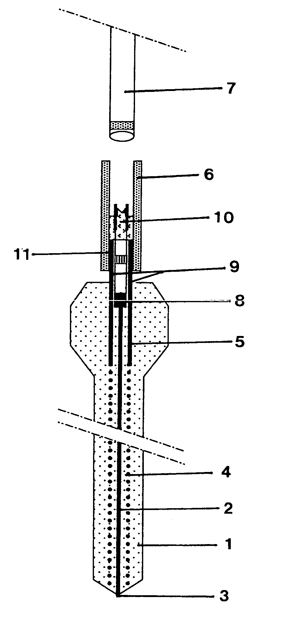
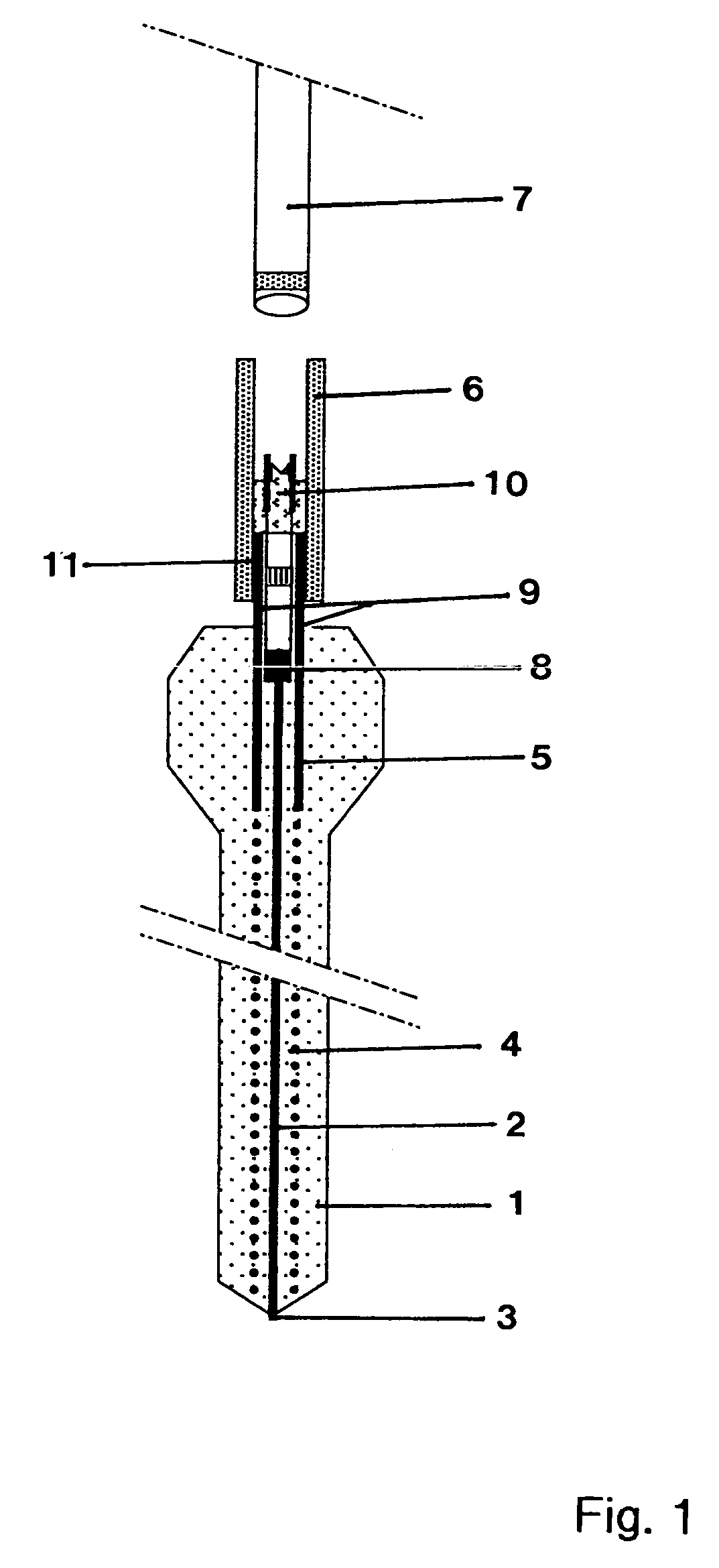
[0016] The consumable body 1 shown in FIG. 1 is essentially formed, for example, from particles of molding sand, inorganic cement, or fly ash, wherein the bonding of the particles is accomplished by pressing or by the use of binding agents. The body 1, along whose longitudinal axis the optical fiber 2 is located, is immersed in a molten metal for measurement. Here, the end 3 of the optical fiber 2 receives measurement signals in the form of optical radiation, from which the temperature of the metal melt is calculated in a known way.

[0017] An abrasion-resistant coating can be applied on the surface of the body 1 to protect the body 1 during handling, especially outside of the molten metal. Within the molten metal the consumable body 1 slowly dissolves, starting from the immersion tip (adjacent the fiber end 3), such that the bonding between the particles of the body 1 slowly breaks up. The process begins at the immersion tip, because this is the first part exposed to the molten meta...


PUM

PropertyMeasurementUnit
temperatureaaaaaaaaaa

Abstract

A device is provided for measuring temperature in molten metals with an optical fiber. The optical fiber is connected directly or indirectly to a measurement instrument and is held by a carrier. The immersion end of the fiber is fed through a body that can be consumed in the metal melt. The consumable body exhibits a consumption rate of at most 10 cm / min, and the consumption rate is approximately equal to or greater than the rate at which the structure of the optical fiber is destroyed.

Description

BACKGROUND OF THE INVENTION [0001] The invention is directed to a device for measuring temperature in molten metals with an optical fiber, which is connected directly or indirectly to a measurement instrument and which is held by a carrier. The immersion end of the fiber is guided by a body that can be consumed in the melt. The invention is further directed to a method for measuring temperature in molten metals with an optical fiber, which is connected directly or indirectly to a measurement instrument and optionally to a detector and which is held by a carrier. [0002] Such devices are known, for example, from European published patent application EP 655 613 A1. In the device described there, the optical fiber has a protective cladding consisting of several layers. The protective cladding dissolves at a rate of 1 to 10 cm per second and therefore, after a relatively short time, the cladding can no longer provide optimum protection for the optical fiber. The protective cladding conta...

Claims


Application Information

Patent Timeline
Patent Type & Authority Applications(United States)
IPC IPC(8): G01J5/00G01J5/04G01J5/08G01K1/14G01K11/32
CPCG01J5/0044G01J5/02G01J5/0205G01J5/041G01J5/0893G01J5/048G01J5/08G01J5/0821G01J5/046G01J5/004G01K11/32
Inventor COLEMAN, THOMAS C. JR.
Owner HERALUS ELECTRO NITE INT NV
Learn More