
Screw

a screw and screw body technology, applied in the field of screws, can solve the problems of increasing the tapping resistance, the actual practice effect of the screw b>3/b> has not been improved obviously, and the cutting speed cannot be quickly removed. , to achieve the effect of less tapping torque, rapid fastening and improved cutting speed

Inactive Publication Date: 2005-08-11
SU KUO TAI
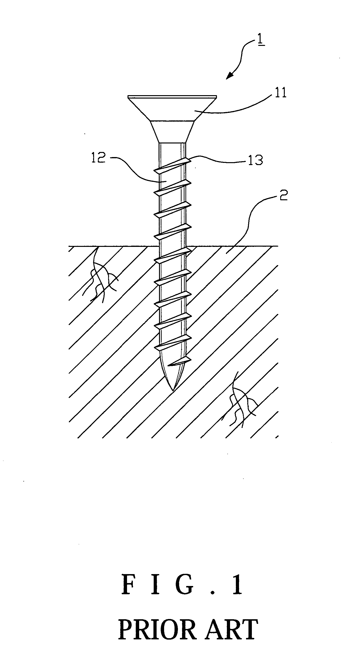
View PDF15 Cites 19 Cited by
  • Summary
  • Abstract
  • Description
  • Claims
  • Application Information

AI Technical Summary

Benefits of technology

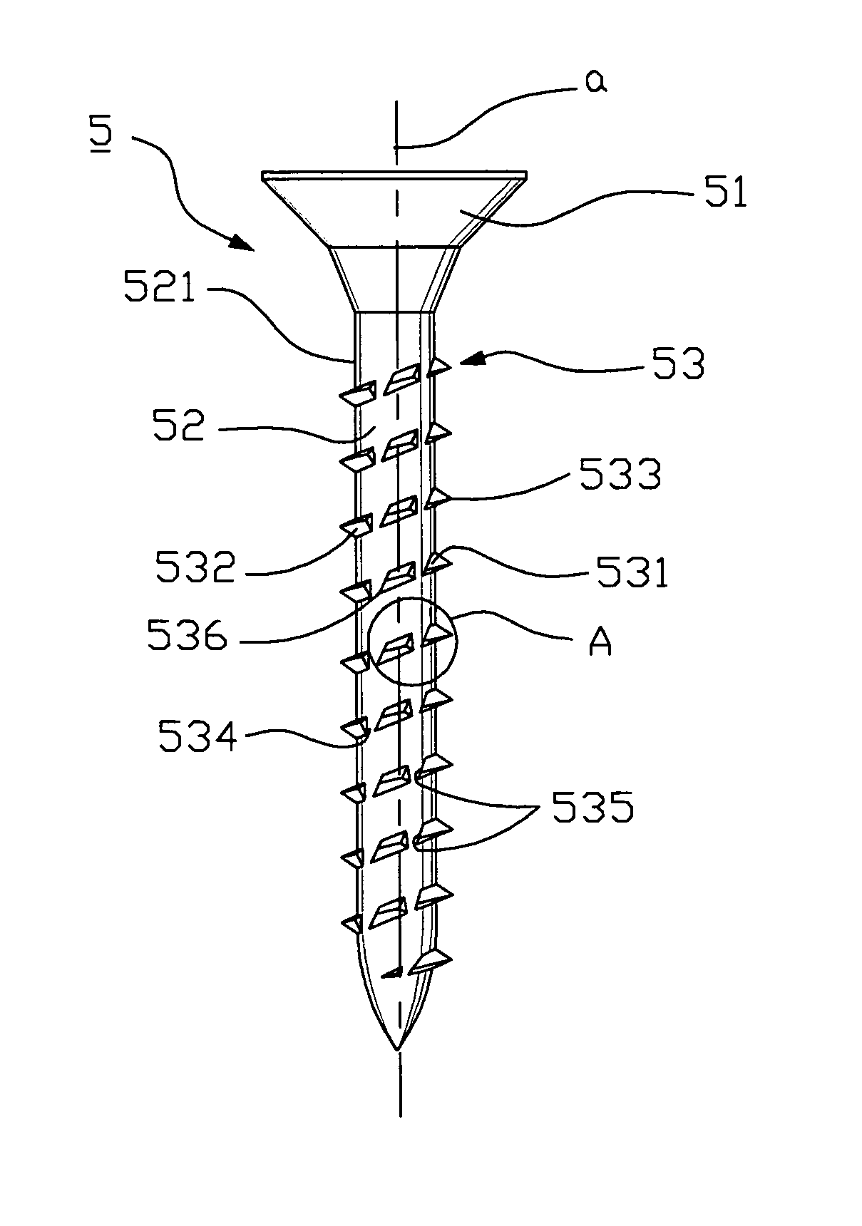
[0012] For archiving the object, the present invention provides a screw comprising of a head, a shank and a thread helically built on the shank; wherein, on the thread there is even number of axial slots formed. Meanwhile, every axial slot is beveled with a back angle to form a sheared section from the upper flight to the low flight to form a cutting edge. As tapping the screw, the cutting lips will improve the cutting speed to get rapid fastening with less tapping torque goal.

Problems solved by technology

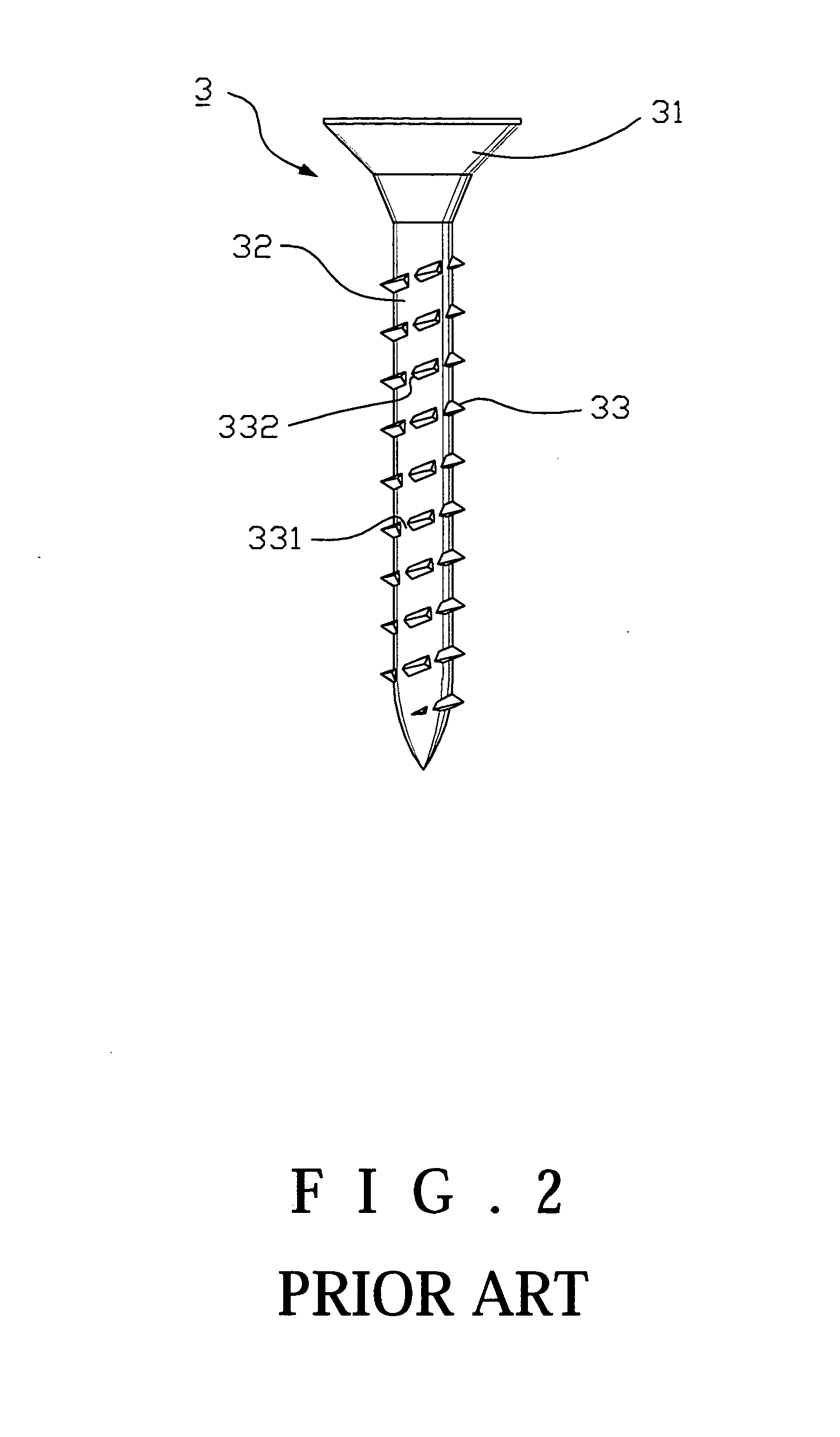
However, due to the facts that the threads 13 cannot cut through the wooden fabric, the wooden fabric chips produced could not be removed out rapidly, and so on, the tapping resistance is increased.
Therefore, the actual practice effect of the screw 3 has not been improved obviously comparing with the conventional screw 1.
Thus the elastic wooden fabric cannot be cut through immediately.

Method used


Image

  • Screw
  • Screw
  • Screw

Examples


Embodiment Construction

[0020] Referring to FIG. 4 and FIG. 5, the first embodiment of the present invention provides a screw 5 consisted of a head 51, a shank 52 under the head 51 in a whole body, and a thread 53 helically built upon the outside trunk of the shank 52. Wherein, said shank 52 has a base circle surface 521 surrounding the axis. The helical thread 53 projects from the base circle surface 521. Said thread 53 is consisted of an upper flight 531, a low flight 532, and a peak 533 on the joint line of the upper and low flights 532533, and an even number of axial slots 534 formed on the thread 53 of the shank 52 in equidistance. The feature is that every axial slot 534 is beveled with a back angle to form a sheared section 535 from the upper flight 531 to the low flight 532, so as to form a cutting edge 536.

[0021] Referring to FIG. 5 and FIG. 6, when secure the screw 5 on an object 6, the worker should vertically press the screw 5 on the surface of the object 6 with the bottom end, and continuousl...


PUM

PropertyMeasurementUnit
Torqueaaaaaaaaaa

Abstract

A screw including a head, a shank under the head in a whole body, and a thread helically built upon the outside trunk of the shank. The thread projects from the circular trunk of the shank and consists of an upper flank, a low flank, and an edge on the joint line of the upper and low flanks, and an even number of axial slots formed on the thread. Every axial slot is beveled with a back angle to form a tilt surface from the upper flank to the low flank to form a cutting edge for facilitating the rapid fastening with a smaller tapping torque.

Description

BACKGROUND OF THE INVENTION [0001] 1. Field of the Invention [0002] This invention relates to a screw, more particularly to a rapid tapping screw with less torque. [0003] 2. Description of the Related Art [0004] In accordance with the conventional screw, as shown in FIG. 1, it includes a head 11 and a shank 12 connecting with the head 11; wherein, there are several helical threads 13 built upon the surface of said shank 12. [0005] When the conventional screw 1 is screwed in a wooden object 2, along with the shank 12 screwing in, by means of the shearing action of the threads 13, it is fastened in there. However, due to the facts that the threads 13 cannot cut through the wooden fabric, the wooden fabric chips produced could not be removed out rapidly, and so on, the tapping resistance is increased. Hence, the worker has to apply bigger tapping force on it in order to implant the screw 1 into the object 2, even if the greater tapping torque applied occurs the screw 1 overloading to b...

Claims


Application Information

Patent Timeline
IPC IPC(8): F16B25/10F16B33/02F16B35/04
CPCF16B25/0015F16B25/10F16B25/0052
Inventor SU, KUO-TAI
Owner SU KUO TAI
Learn More