Rotary piston machines comprising a displaceable inner housing

a technology of displaceable inner housing and rotary piston machine, which is applied in the direction of machines/engines, rotary/oscillating piston pump components, liquid fuel engines, etc., can solve the problems of disproportionate increase in the manufacturing cost of precise, rotor relative to one another increase exponentially, and it is not possible to reduce gap losses at economically justifiable costs. , to achieve the effect of reducing gap losses

Active Publication Date: 2005-08-11
ROBERT BOSCH GMBH
View PDF6 Cites 13 Cited by
  • Summary
  • Abstract
  • Description
  • Claims
  • Application Information

AI Technical Summary

Benefits of technology

[0003] In comparison with the above, the inventive rotary piston machine has the advantage that, due to the arrangement of the inner housing, which can be shifted freely in the axial and radial directions, the inner housing is centered relative to the rotors, so that the dimensions of the gap between the components of the rotary piston machine, which can be moved relative to one another (power part, shut-off part, inner housing) and are arranged to form a seal, can be averaged, as a result of which the gap losses are reduced. This is achieved owing to the fact that the rotors, which have a spherical external shape and are centered, on the one hand, by a shaft, for example, the drive shaft of a motor (power part) that is flanged to the rotary piston machine and, on the other, the control head of the rotary piston machine (shut-off part), are surrounded by an inner housing with a spherical recess. With a cylindrical borehole, which goes over into the spherical recess, the inner housing freely movably takes up the rotor, the rotor being centered on the shank of the control head. The spherical recess is to accommodate the one rotor, which is disposed on shank and engages the other rotor, seated on the shank of the control head, at an axial angle. An opening in the spherical part of the inner housing permits the shaft, as well as the shank of the rotor (power part) fastened thereon, to be passed through. In addition, the inner housing is prevented from backing away from the control head, for example, by a cone, which surrounds the shank of the rotor rotating with the shaft, and prevented from rotating along by a protection against torsion, which can be shifted freely in the axial and radial directions, for example, by springs, which are disposed on the outside of the inner housing and engage recesses at the outer housing. Pressure equalization between the inside and the outside of the inner housing is produced through openings over a portion of the periphery at the inner housing which, depending on the type of operation, function as an inlet or an outlet of the conveying or driving fluid, so that the pressure between the inner housing and the housing is the same as that within the inner housing and that the pressure between the housing and the inner housing is higher than the static pressure in the gap between the outer circumferential surface of the rotors and of the inner surface of the inner housing during developing flow through the gap, so that, by these means, an additional sealing action is achieved, in that the inner housing is pressed all around on the rotors by the resulting pressure forces.

Problems solved by technology

However, such machines have the disadvantage that, especially when the overall dimensions become smaller, the gap losses between the regions in the interior of such machines, which are acted upon with different pressures and can be used as pumps or motors, increase and, due to methods such as the manufacture of components with lower tolerances, there is a disproportionate increase in the manufacturing costs for producing precise, meshing rotors and the associated housing, as a result of which the necessary expense for centering the rotors relative to one another increases exponentially and it is not possible to reduce these gap losses at economically justifiable costs.

Method used


Image

  • Rotary piston machines comprising a displaceable inner housing
  • Rotary piston machines comprising a displaceable inner housing

Examples


Embodiment Construction

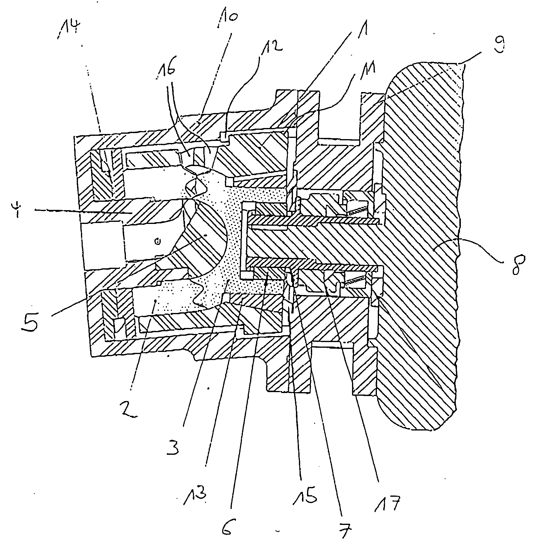
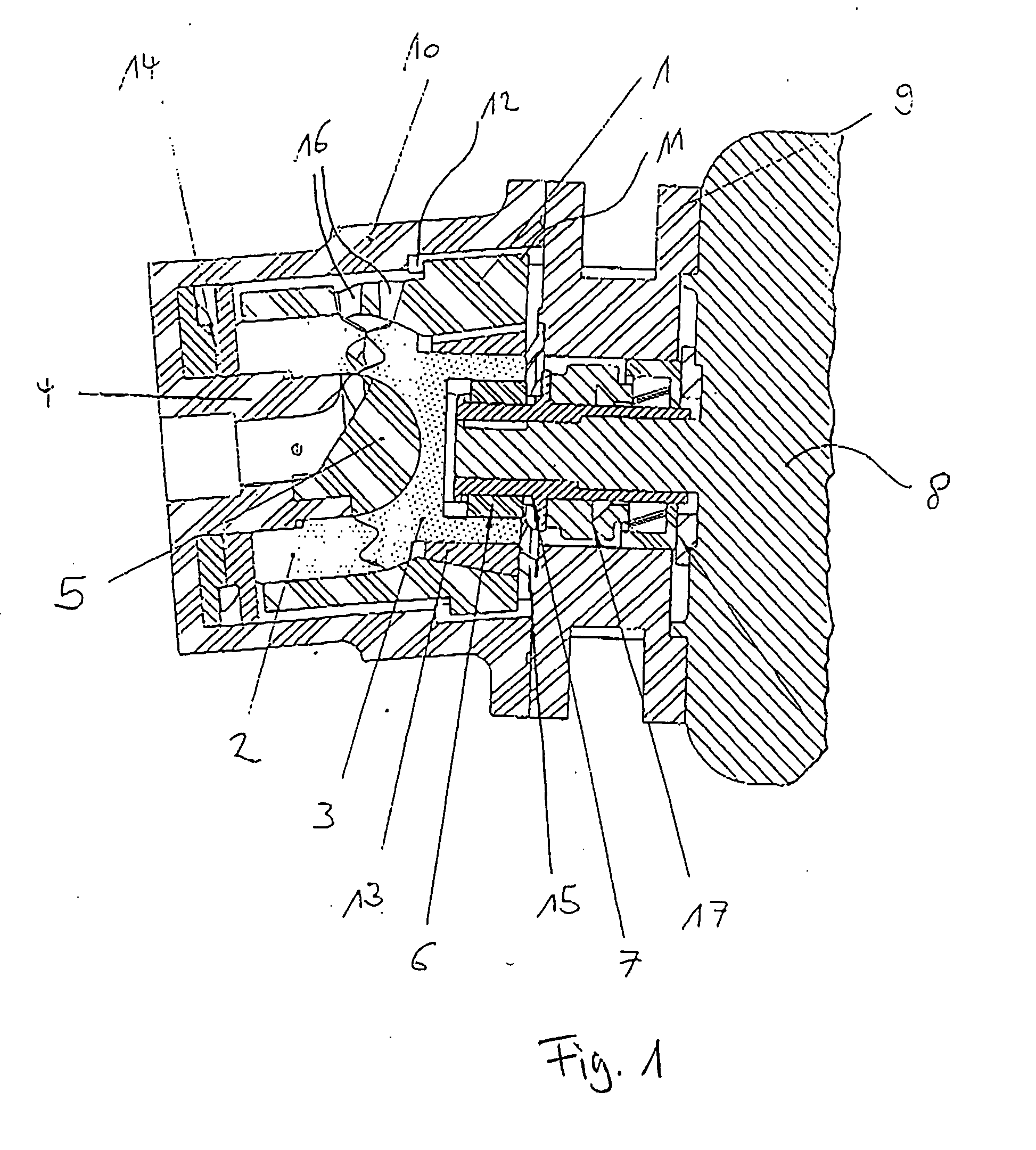
[0008] The rotors of a rotary piston machine, the shut-off part 2 and the power part 3, engage one another at an axial angle, so that chambers are formed between the shut-off part 2 and the power part 3. The chambers have volumes variable over the angle of rotation for conveying fluids or gases.

[0009] With a borehole accommodating the shank 4 of the control head 5, the shut-off part 2 is disposed rotatably about the longitudinal axis of the shank 4. On the side facing the shut-off part 2, the power part 3 has a central, spherical recess for accommodating the control head 5.

[0010] By means of an adjusting spring 6 and a shaft extension 7, the shank of the power part 3 is fastened on the shaft of a motor 8. The housing 10 is fastened to the motor 8 over a flange 9.

[0011] The two rotors (shut-off part 2 and power part 3), which are fixed in their position by the shank 4 of the control head 5 and the shaft of the motor 8, are surrounded by an inner housing 1. The inner housing 1 can ...


PUM


Abstract

In a rotary piston machine with an inner housing and rotors, the axes of the rotors are disposed at an angle to one another in order to equalize manufacturing tolerances and to reduce gap losses of such machines.

Description

BACKGROUND OF THE INVENTION [0001] The invention relates to a rotary piston machine. The manufacture of rotary piston machines with power parts and shut-off parts with axes arranged at an angle to one another is known. For these, the rotors, at least one power part and one shut-off part occupy a spherical volume (DE 42 41 320 C2) or correspond to the volume of a spherical washer (198 37 729 A1). [0002] However, such machines have the disadvantage that, especially when the overall dimensions become smaller, the gap losses between the regions in the interior of such machines, which are acted upon with different pressures and can be used as pumps or motors, increase and, due to methods such as the manufacture of components with lower tolerances, there is a disproportionate increase in the manufacturing costs for producing precise, meshing rotors and the associated housing, as a result of which the necessary expense for centering the rotors relative to one another increases exponentiall...

Claims


Application Information

Patent Timeline
Patent Type & Authority Applications(United States)
IPC IPC(8): F01C3/08F01C9/00F01C21/10
CPCF01C3/085F04C2230/601F01C21/106F01C9/005
Inventor ARNOLD, FELIX
Owner ROBERT BOSCH GMBH
Why Eureka
Try Eureka