
Drive sprocket wheel slide restricting structure of bicycle transmission

a technology of sprocket wheel and bicycle transmission, which is applied in the direction of cycle equipment, transportation and packaging, gearing, etc., can solve the problems of cable operation becoming heavy and the smooth movement impaired, and achieve the effect of high degree of accuracy and speed chang

Inactive Publication Date: 2005-08-11
HONDA MOTOR CO LTD
View PDF8 Cites 13 Cited by
  • Summary
  • Abstract
  • Description
  • Claims
  • Application Information

AI Technical Summary

Benefits of technology

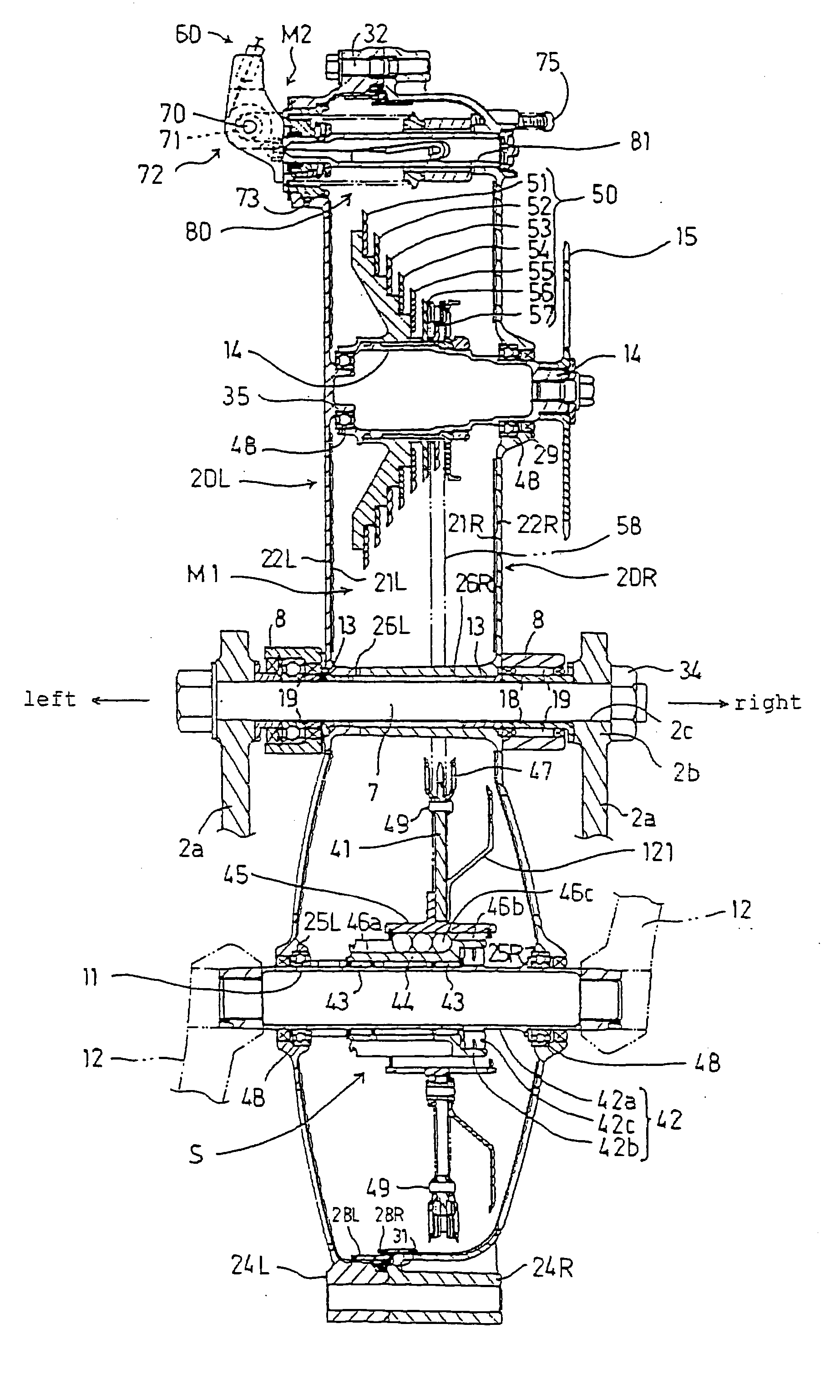
[0008] In view of such a problem, it is an object of the present invention to provide a transmission for a bicycle in which the speed-change operation can be achieved with a light force, and the speed can be changed smoothly with a high degree of accuracy.
[0010] Since the roller journaled by the operating pin rotates in the guide hole when the operating pin is moved while being guided through the guide hole by the speed-change operation via the wire, the operating pin can be moved smoothly without a sliding friction, whereby the speed-change operation can be performed with a light force and the speed can be changed smoothly with a high degree of accuracy.
[0012] When the operating pin is moved while being guided through the guide holes by the speed-change operation via the wire, a pair of the rollers journaled by the both ends of the operating pins are rotated in the opposite direction from each other while coming into contact with the inner surfaces of a pair of the guide holes. Thus, the operating pins can be moved smoothly without sliding friction, and the speed-change operation can be achieved with a light force, and the speed can be changed smoothly with a high degree of accuracy.

Problems solved by technology

Thus, a smooth movement is impaired and a cable operation becomes heavy.

Method used


Image

  • Drive sprocket wheel slide restricting structure of bicycle transmission
  • Drive sprocket wheel slide restricting structure of bicycle transmission
  • Drive sprocket wheel slide restricting structure of bicycle transmission

Examples


Embodiment Construction

[0038] An embodiment of a transmission according to the present invention illustrated in FIG. 1 to FIG. 21 will be hereinafter explained.

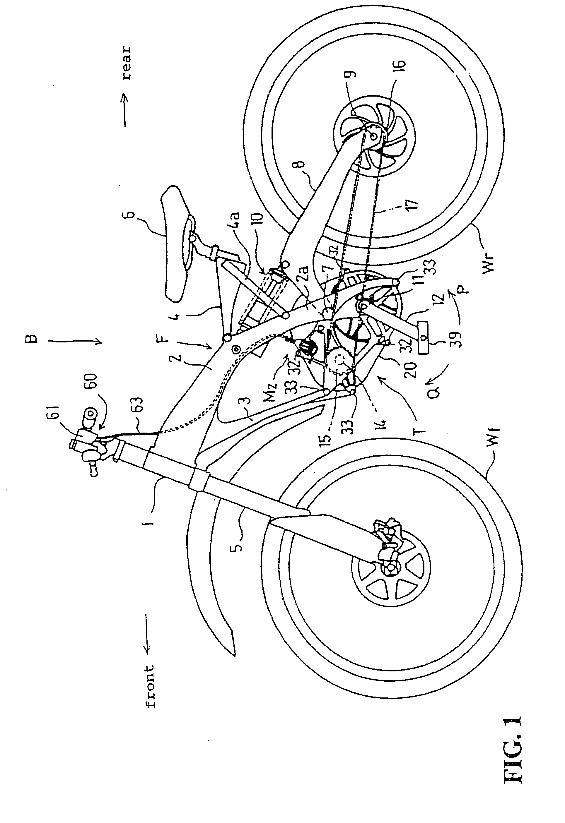
[0039]FIG. 1 is a left side view of a bicycle B in which the transmission according to the present invention is used. The bicycle is a downhill bicycle and is used in a competition wherein players compete against time for descending an unpaved course which includes high-speed corners and jump sections in a woodland path or the like.

[0040] A vehicle body frame F of the bicycle B includes a pair of left and right main frames 2 which extend rearwardly, obliquely and downwardly from a head pipe 1, a down tube 3 which extends rearwardly, obliquely and downwardly from front end portions of both main frames 2 below the front end portions, and a saddle frame 4 which extends rearwardly from center portions of respective main frames 2.

[0041] The saddle frame 4 which supports a saddle 6 is supported on a stay 4a which is interposed between the saddle frame...


PUM


Abstract

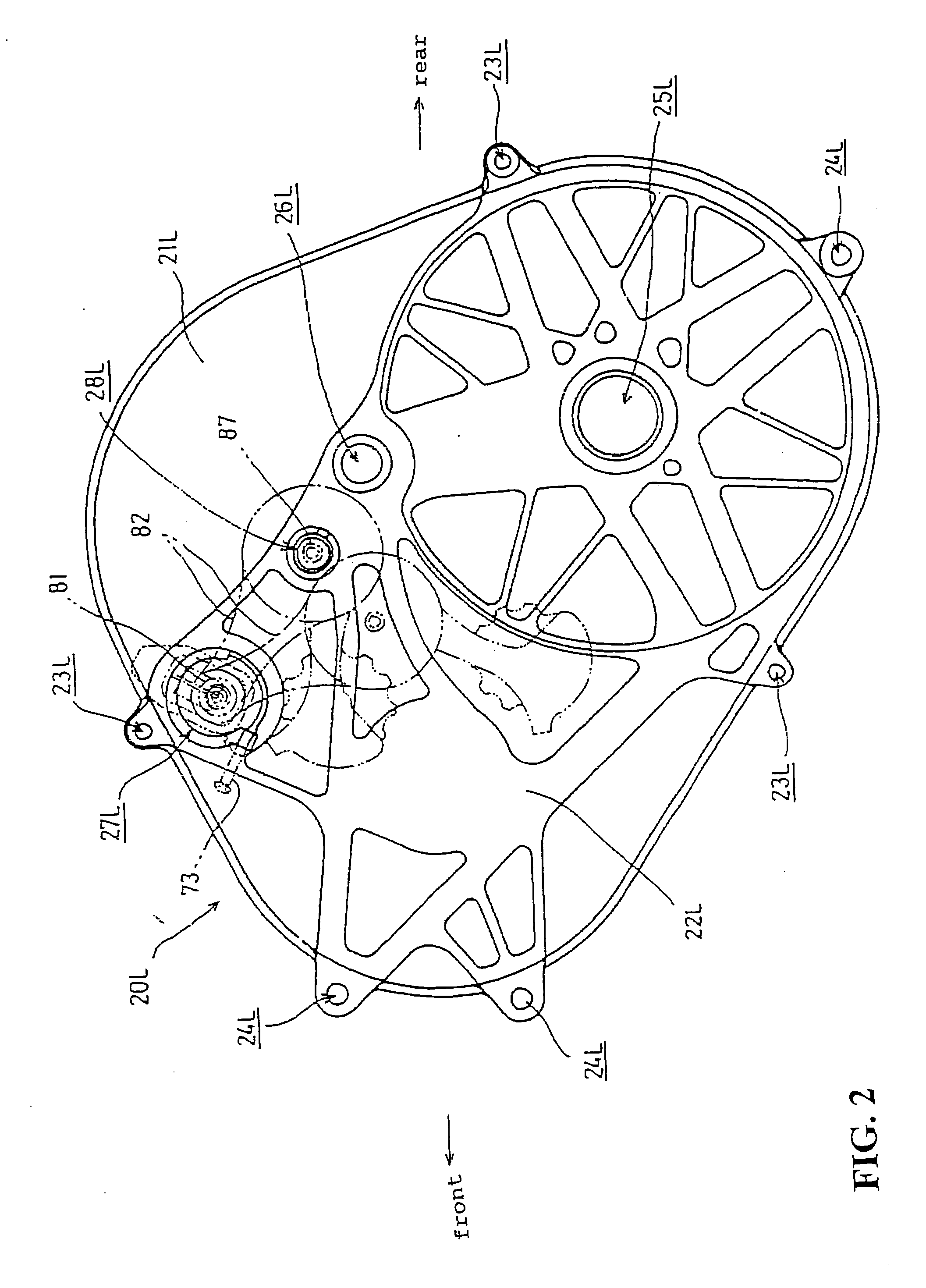
A transmission for a bicycle includes a derailleur shaft supported by a case member. A derailleur arm is movably journaled by the derailleur shaft. A guide rotational body is rotatably supported by the derailleur arm and an endless power transmission belt is wound therearound. The endless power transmission belt is shifted among a plurality of rotational body elements which constitute a speed-change rotational body for changing the speed-change ratio. An operating pin is connected to a wire which moves in the fore-and-aft direction in accordance with the speed-change operation so that the derailleur arm is rotated with respect to the derailleur shaft and translated toward the center axis of the derailleur shaft by the operating pin being moved while being guided through the guide hole by the speed-change operation via the wire. A roller is rotatably journaled by the operating pin is rotatably fitted in the guide hole.

Description

BACKGROUND OF THE INVENTION CROSS-REFERENCE TO RELATED APPLICATIONS [0001] The present application claims priority under 35 USC 119 to Japanese Patent Application No. 2004-034099 filed on Feb. 10, 2004 the entire contents of which are hereby incorporated by reference. FIELD OF THE INVENTION [0002] The present invention relates to a transmission for a bicycle provided with a derailleur. DESCRIPTION OF BACKGROUND ART [0003] In a transmission for a bicycle, a derailleur, which is simple in structure and low in cost, is used as a mechanism for shifting a chain wound around a drive sprocket and a driven sprocket for changing the speed among a plurality of sprockets provided, for example, in the driven sprocket. [0004] For example, a derailleur for a transmission for a bicycle disclosed in Japanese Patent No. 2654101, see FIGS. 3 and 5, that includes a guide member fixed to an upper body provided in a frame of a bicycle in the axial direction and the rotational direction. A control lever ...

Claims


Application Information

Patent Timeline
Patent Type & Authority Applications(United States)
IPC IPC(8): B62M9/1242B62M9/1248B62M9/1344B62M9/135B62M11/14B62M25/02F16H9/00F16H9/24F16H61/36F16H63/00
CPCB62M9/131F16H9/24B62M11/145
Inventor MATSUMOTO, SHINYAINOUE, NAOKI
Owner HONDA MOTOR CO LTD
Learn More