Silicone rolling pin

a technology of silicon dioxide and rolling pins, applied in the field of rolling pins, can solve the problems of uneven temperature, less efficiency, and more time to complete the job, and achieve the effect of avoiding the disadvantages of known rolling pins

Active Publication Date: 2005-08-11
FIESTA PRODS
View PDF9 Cites 13 Cited by
  • Summary
  • Abstract
  • Description
  • Claims
  • Application Information

AI Technical Summary

Benefits of technology

[0007] The inventors have discovered that the disadvantages of known rolling pins may be avoided by a rol...

Problems solved by technology

(1) It takes more time to complete the job and therefore is less efficient.
(3) When the dough sticks to the pin and needs to be removed, the weight distributio...

Method used


Image

  • Silicone rolling pin
  • Silicone rolling pin
  • Silicone rolling pin

Examples


Embodiment Construction

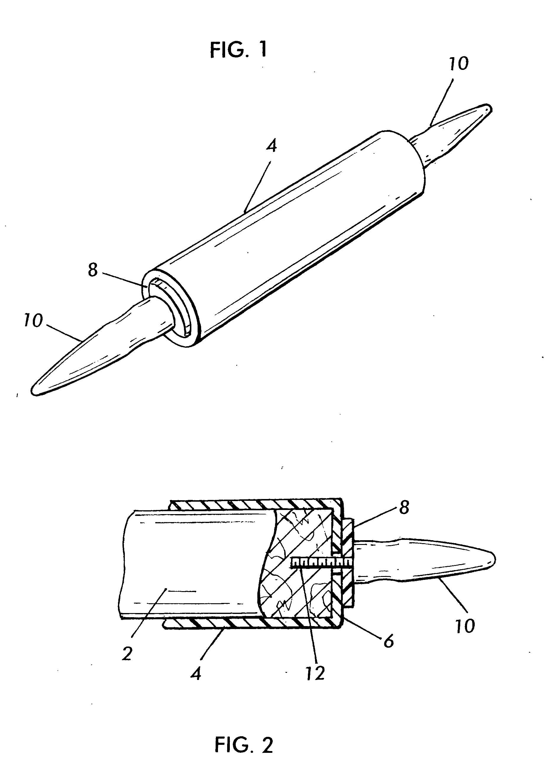
[0028]FIG. 1 is a perspective view of a silicone rolling pin, including a silicone jacket 4, caps 8 at the end regions of the silicone jacket 4, and handles 10. Other features of the rolling pin not specifically discussed, such as the core 2, may be substantially conventional.

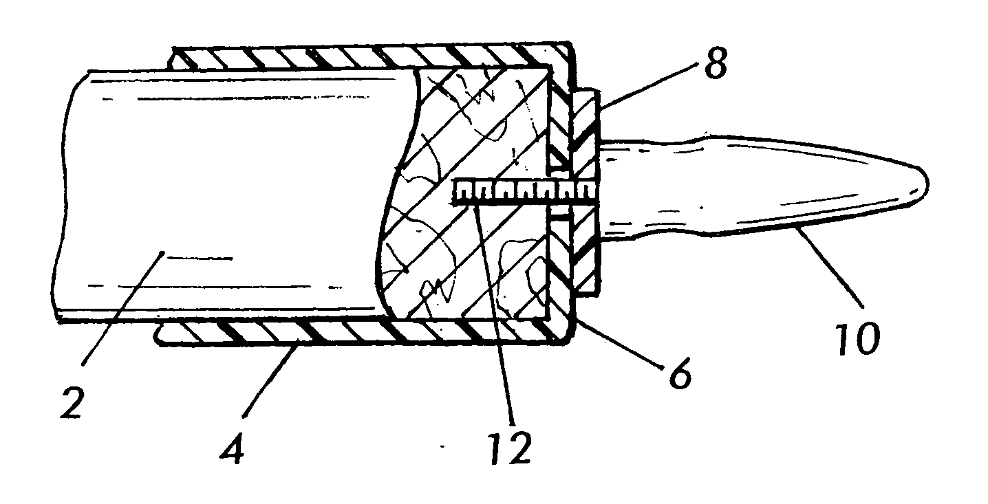
[0029]FIG. 2 shows a cross-section of one end of the rolling pin, illustrating the various layers including the core 2, the silicone jacket 4, the end regions 6 of the silicone jacket, the caps 8 over the end regions (or in another embodiment, not shown, abutting the end regions) 6 of the silicone jacket and handles 10 with a screw threaded (or dowel) support 12 passing through the cap 8 and into the core 2, as one example of a mode of how to attach the handle to the rolling pin.

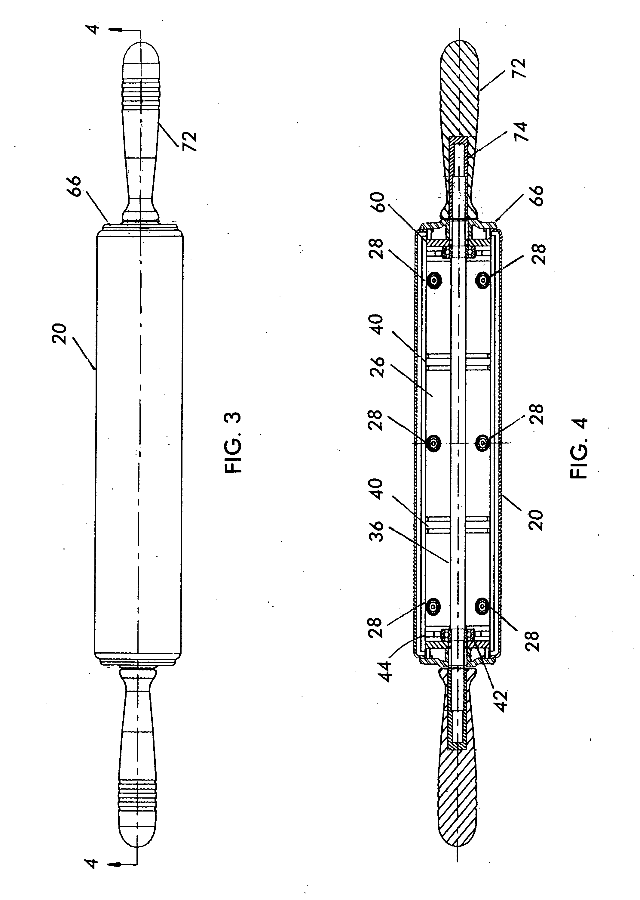
[0030] A second embodiment of the invention is shown in FIGS. 3, 4 and 5. FIG. 3 is a side view of a rolling pin having a jacket 20, end caps 66 and handles 72 similar to those in the first embodiment. Referring now to FIGS. 4 and 5, ...


PUM


Abstract

A rolling pin including a core, a silicone-containing jacket over the core defining a rolling surface. The jacket may be of such length and so positioned on the core as to define end regions of the jacket extending beyond the ends of the core; the jacket end regions being folded inward over the ends of the core; a cap securing to the core each folded inward end region of the jacket. A handle may be at each end of the core.

Description

CROSS-REFERENCE TO RELATED APPLICATIONS [0001] This application is based upon and claims priority of U.S. Provisional Patent Application Ser. No. 60 / 544,617 filed by Gregory C. Dua et al. on Feb. 13, 2004 (PP / 4525-4) and U.S. Provisional Patent Application Ser. No. 60 / 542,308 filed by Gregory C. Dua et al. on Feb. 5, 2004 (PP / 4525-2), the disclosures of which are incorporated by reference.BACKGROUND OF THE INVENTION [0002] 1. Field of the Invention [0003] The invention relates to a rolling pin, and more particularly to a rolling pin which uses the non-stick properties of silicone on an exterior jacket of the rolling pin. [0004] 2. Background Art [0005] The most important use of a rolling pin is for rolling dough for making pastries, etc. It is vital that the dough does not stick to the pin when rolling. Dough sticking to the pin has the following disadvantages. (1) It takes more time to complete the job and therefore is less efficient. (2) Before and during rolling, flour must be ad...

Claims


Application Information

Patent Timeline
IPC IPC(8): A21C3/02
CPCA21C3/021
Inventor DUA, GREGORY C.BLOOM, EDWARD J.SADOFSKY, RICK
Owner FIESTA PRODS
Why Eureka
Try Eureka