Kitchen ventilation degreasing system

Inactive Publication Date: 2005-08-18
MARSHALL JOHN +3
View PDF8 Cites 35 Cited by
  • Summary
  • Abstract
  • Description
  • Claims
  • Application Information

AI Technical Summary

Benefits of technology

[0026] The liquid run-off from the degreasing process drains into the existing grease collection system, but this is

Problems solved by technology

However, air-borne grease as it cools commonly accumulates on the inside walls of the ventilation ducts, thereby creating a grease-fire hazard.
The process is cumbersome, messy and typically exposes workers to hazardous chemicals.
In addition, visibility within the duct is minimal and verification of

Method used


Image

  • Kitchen ventilation degreasing system
  • Kitchen ventilation degreasing system
  • Kitchen ventilation degreasing system

Examples


Example

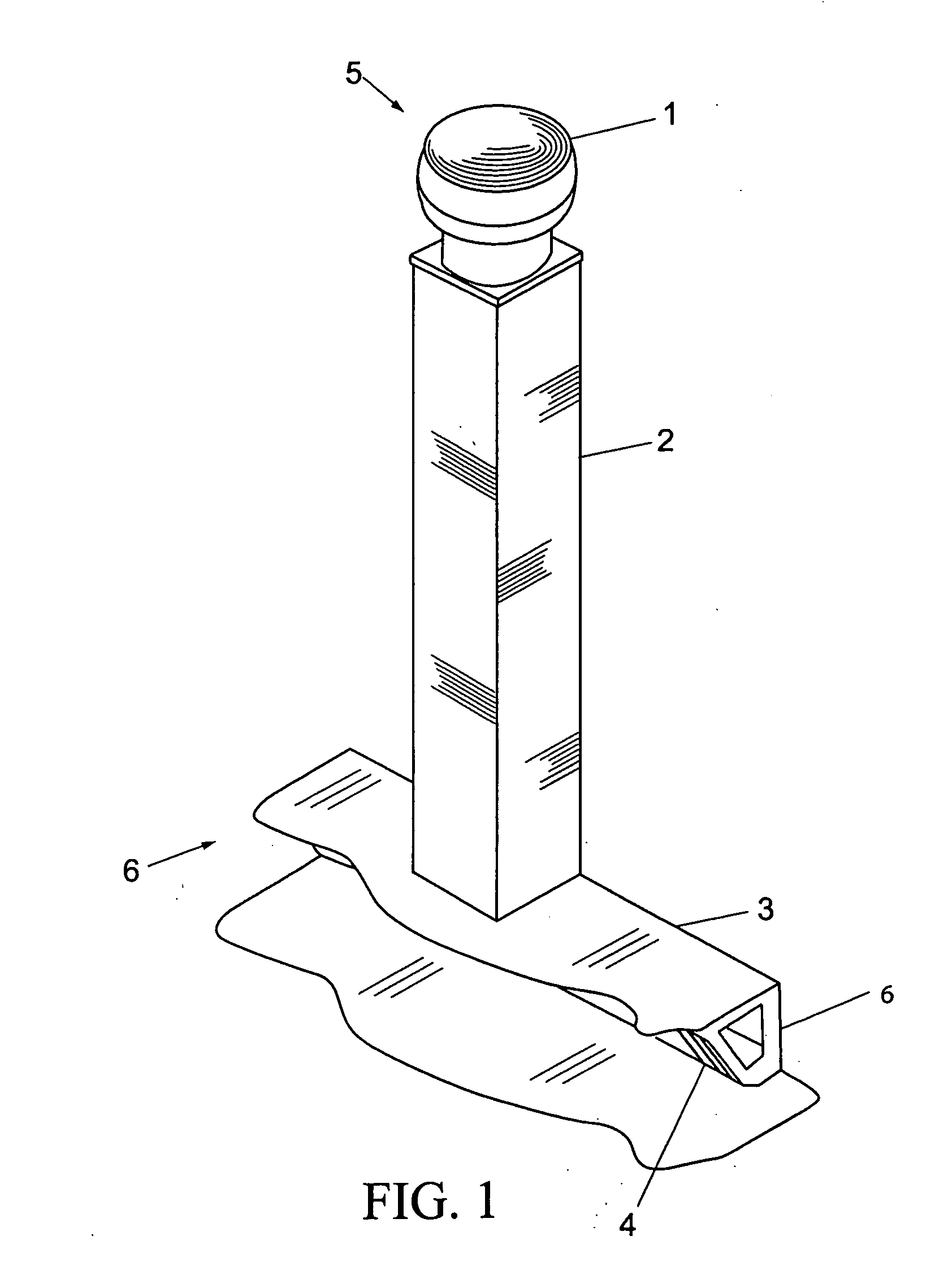
[0047] The present invention is described in the context of a conventional kitchen ventilation system with an exhaust end 5 and an air intake end 6 (FIG. 1), an electronically controlled exhaust fan 1 at exhaust end 5, a rectangular vertical duct 2, and a kitchen hood 3 with removable flue filters 4 at air intake end 6. In operation, the exhaust fan 1 pulls kitchen air (including smoke and airborne grease) into the hood 3 through flue filters 4, into the duct 2 and out exhaust fan 1. One skilled in the art should appreciate that the present invention can be easily adapted for use with any similar ventilation system, including systems using cylindrical or non-vertical ducting, without departing from the scope and spirit of the present invention.

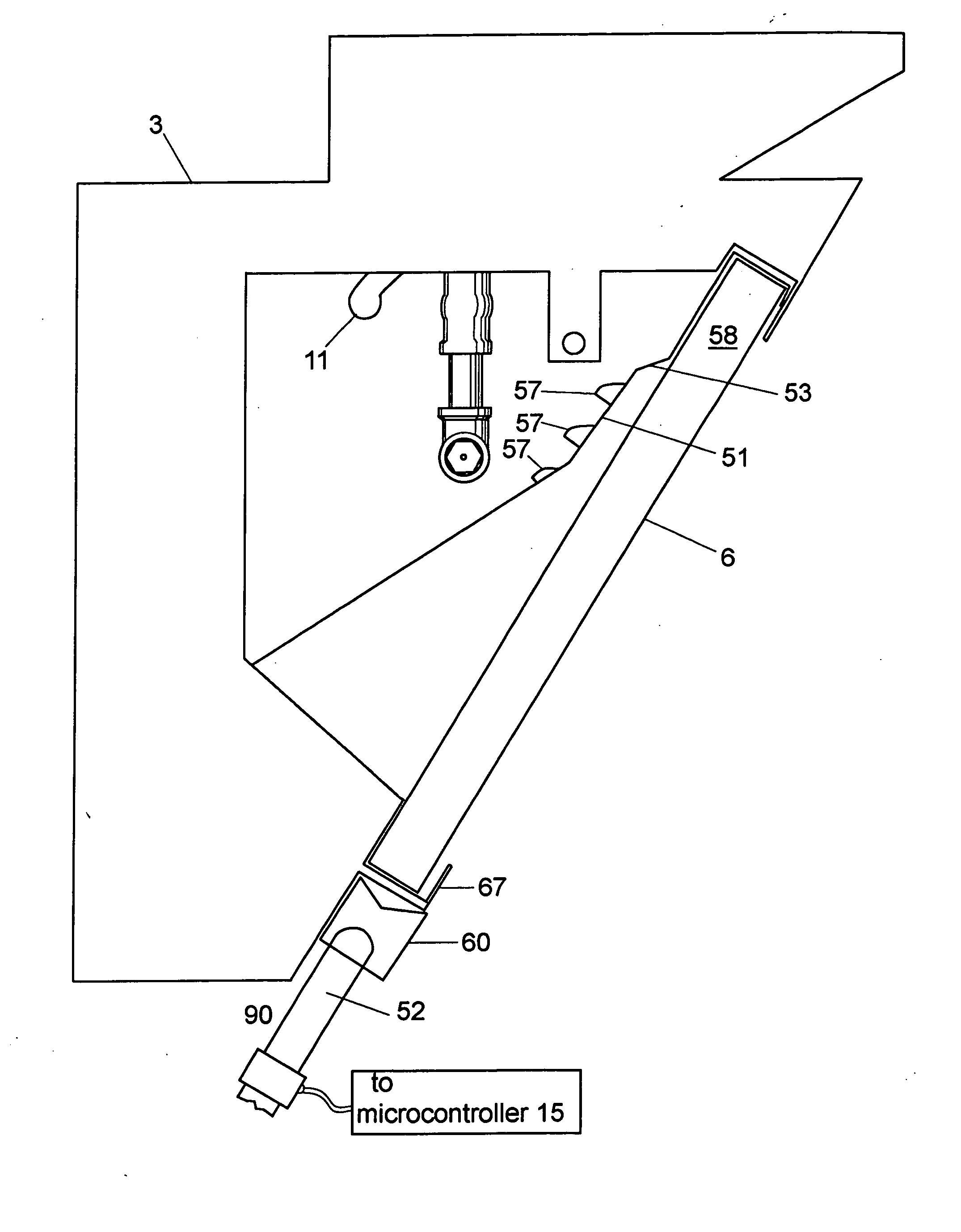
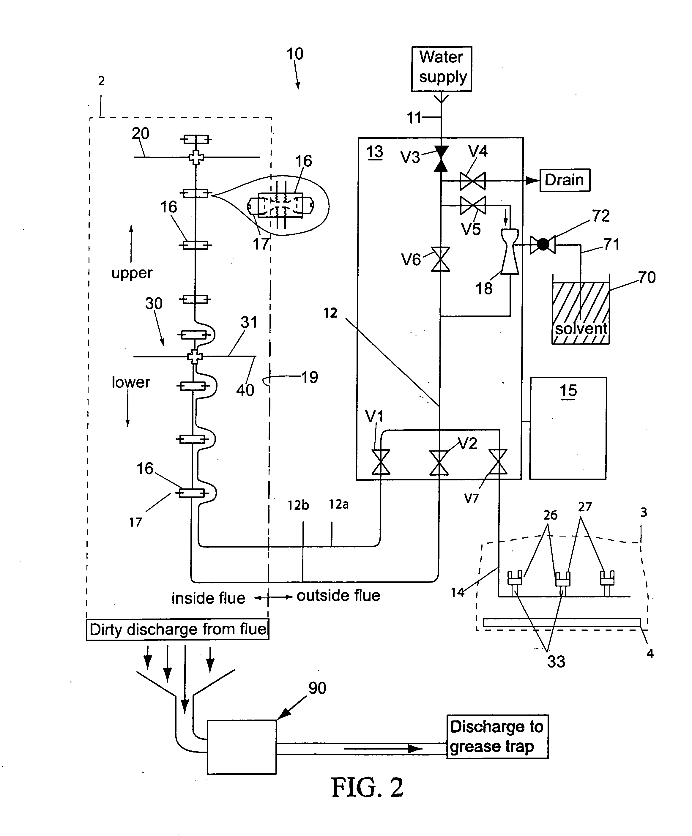
[0048] The kitchen ventilation degreasing system according to the present invention includes two main components, a cleaning mechanism 10 (described below with reference to FIGS. 2-14) with support features, and a drainage mechanism 50 (see F...


PUM


Abstract

The present invention is a permanently installed automatic kitchen ventilation degreasing system. The system includes a cascading cleaning mechanism and drainage mechanism. A water feed tube carries water and cleaning agents to a conduit secured and centered within the ventilation ducts. The water and cleaning agents are sprayed in a cascading manner along the inner surface of the duct by spray nozzles located on nozzle blocks spaced at intervals along the conduit. The flow of solvent or rinse water through the nozzles is controlled by solenoid valves which are controlled by a programmable controller. The liquid run off is collected by a deflector and drained.

Description

CROSS-REFERENCE TO RELATED APPLICATIONS [0001] The present application derives priority from Provisional Patent Application No. 60 / 534,325 filed Jan. 5, 2004.BACKGROUND OF THE INVENTION [0002] 1. Field of the Invention [0003] The present invention relates generally to the field of spray applicators for cleansing the interior surfaces of enclosed spaces and, more particularly, to a fully automated spray degreasing system for cleansing elongated enclosed spaces such as in kitchen ventilation systems and the like. [0004] 2. General Background [0005] Kitchen ventilation ducts are typically required by code to remove smoke, air borne grease, and by-products of cooking from commercial kitchen areas and particularly from the area directly over the stove-tops. However, air-borne grease as it cools commonly accumulates on the inside walls of the ventilation ducts, thereby creating a grease-fire hazard. Periodic degreasing of the kitchen ventilation ducts on a regular basis is recommended and...

Claims


Application Information

Patent Timeline
IPC IPC(8): F24C15/20
CPCF24C15/2057
Inventor MARSHALL, JOHNWAY, JOELIPFORD, KEITHLIPFORD, BRIAN
Owner MARSHALL JOHN
Why Eureka
Try Eureka