Method and system for enhanced modulation of video signals

a video signal and enhanced modulation technology, applied in the field of enhanced modulation of video signals, can solve the problems of increasing the difficulty of an unauthorized party interfering with or intercepting the carrier signal, prone to being stripped, and using broughton and other methods of encoding carrier signals may not be robust enough, so as to increase the detectability of the carrier signal and increase the alteration of the video signal

Active Publication Date: 2005-08-18
ADVOCADO INC
View PDF27 Cites 1 Cited by
  • Summary
  • Abstract
  • Description
  • Claims
  • Application Information

AI Technical Summary

Benefits of technology

[0018] The following improvements for modulating a video signal with a carrier signal improve upon the methods and apparatus previously disclosed in Broughton, Ciardullo and Chupp. The present invention relates to methods and apparatus for optimizing a carrier signal to be inserted in an active portion of a video signal so as to increase the detectability of the carrier signal without noticeably increasing the alteration of the video signal to a viewer.

Problems solved by technology

However, these scan lines may already contain other carrier signals such as signals that represent cueing information, timing information or closed captioning information and are prone to being stripped by programming operators prior to broadcast.
The use of Broughton and other methods of encoding carrier signals may not be sufficiently robust for embodiments where there is a possibility that the carrier signal will be detected, altered or removed by an unauthorized party.
In addition, the spreading of the spectrum from a single frequency to multiple frequencies dramatically increases the difficulty of an unauthorized party interfering with or intercepting the carrier signal.
Accordingly, there is a need in the art to modulate a video signal with a carrier signal over a spread spectrum wherein the presence of the carrier signal is detectable without paired lines, such that it is difficult to remove the carrier signal from the video signal without rendering the video signal unwatchable and the resulting picture distorted.
Since one of the advantages of using Broughton is its invisibility to the human eyesight, any tendency of viewing the effects of the carrier signal is undesirable.
However, lowering the overall signal intensity decreases the reliability of detecting the carrier signal.
Modulated video signals are subject to tampering as the signal may be resized or otherwise altered such that the video signal is de-interlaced.
When the video signal is re-interlaced, it may become altered such that the line to line differences between a first and a second field may be read erroneously by a detector such that the carrier signal is shifted so that it is no longer on the desired lines or is on undesirable lines.

Method used


Image

  • Method and system for enhanced modulation of video signals
  • Method and system for enhanced modulation of video signals
  • Method and system for enhanced modulation of video signals

Examples


Embodiment Construction

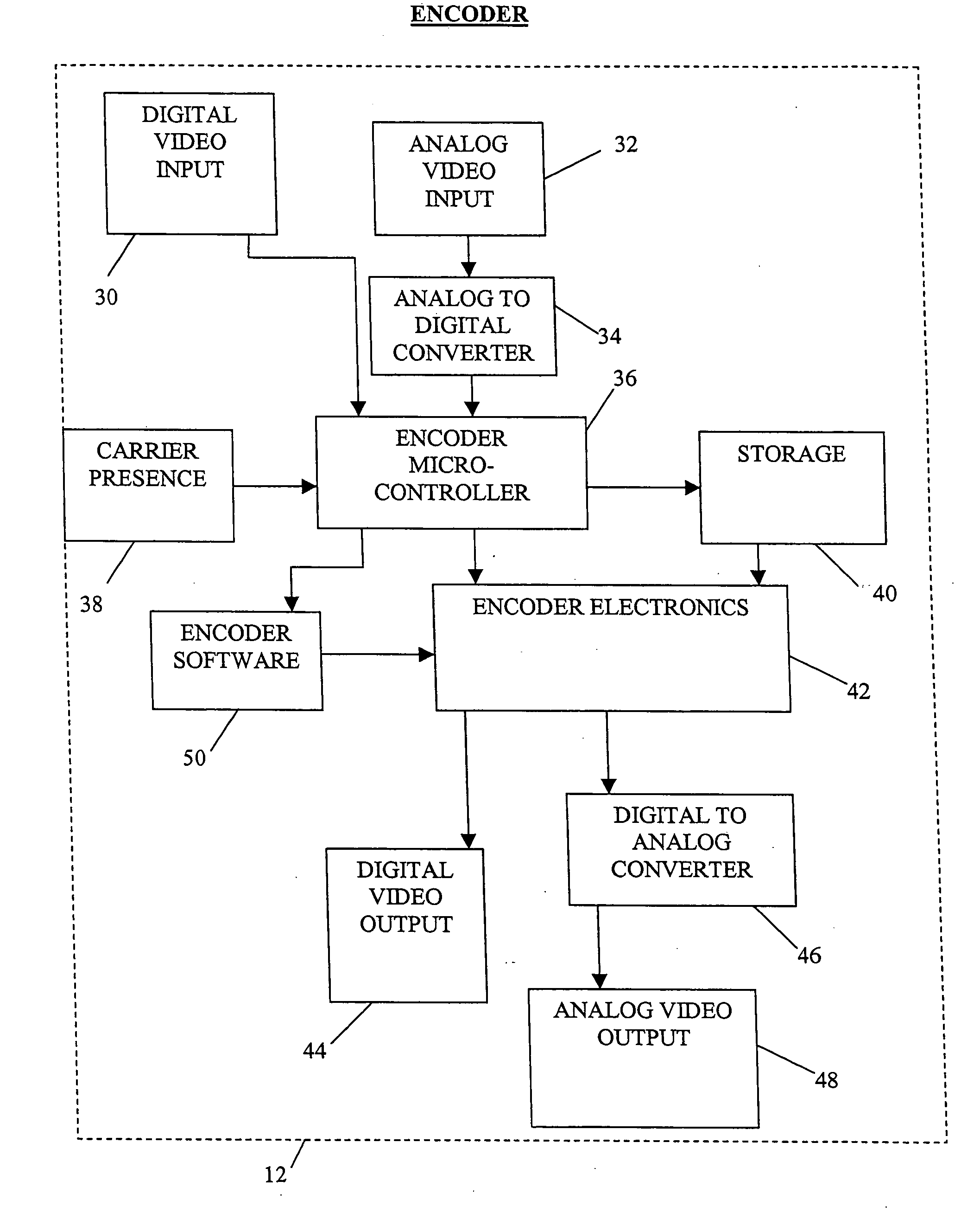
[0055] Referring to the drawings, a method, apparatus and system for optimal modulation of a carrier signal within an active portion of a video signal in a manner that the carrier signal cannot be easily stripped and the detectability of the carrier signal is increased without noticeably increasing the alteration of the video signal to a viewer is illustrated in FIGS. 1-29.

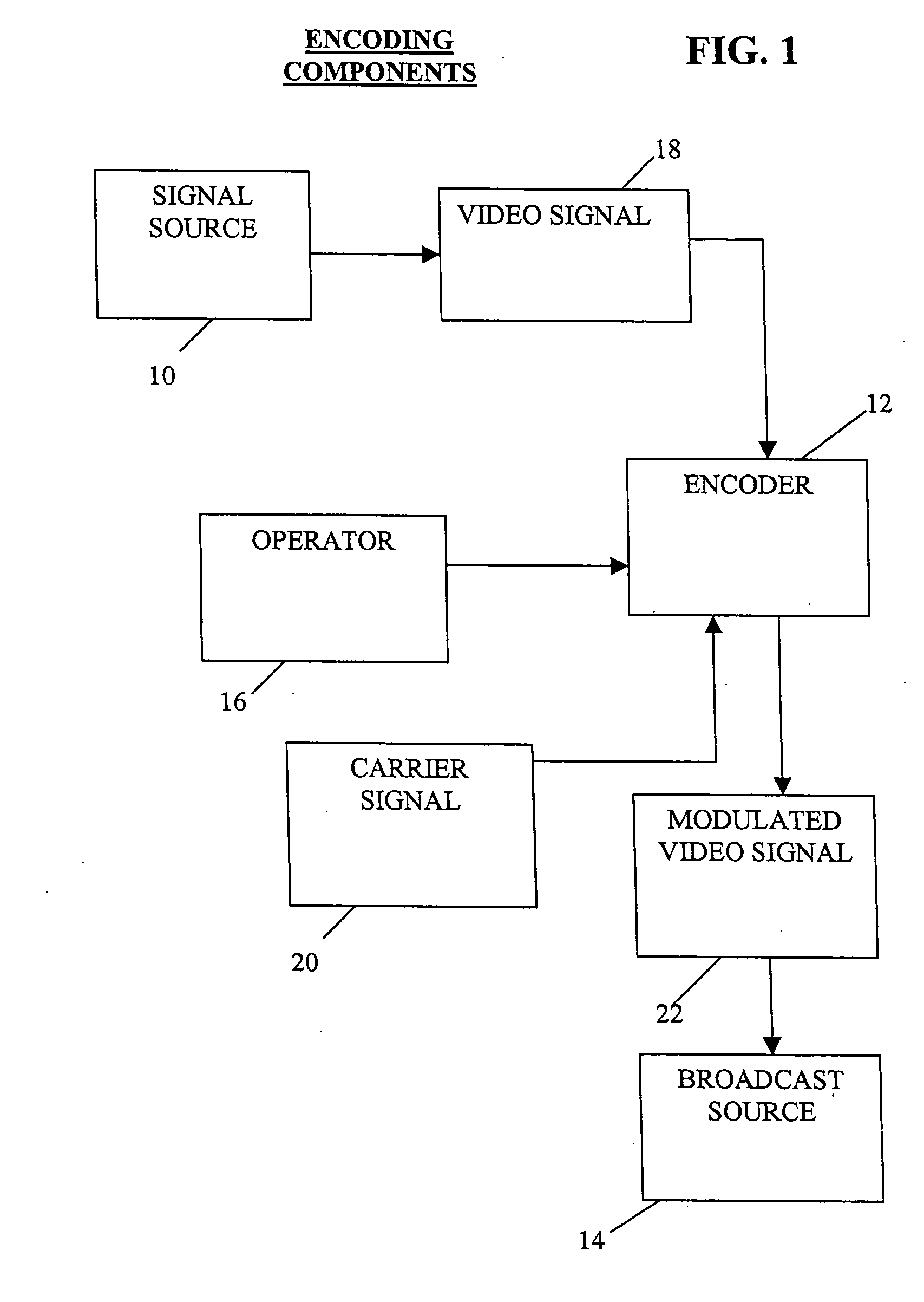
[0056] Referring to FIG. 1, a video signal 18 is transmitted from a signal source 10 to an encoder 12. Video signal 18 is preferably an analog video signal in NTSC (National Television Standards Committee) format, but may be other video signals or video signal formats compatible with the present invention. Signal source 10 is typically a professional grade video tape player with a video tape containing a video program, but may also be other sources of video including a camcorder or a digital versatile disc (DVD) player with a DVD video containing a video program. Encoder 12 is described in greater detail below.

[...


PUM


Abstract

A method for encoding a carrier signal in a video signal, the video signal having one or more frames, the frames each having a first field and a second field, the first field and the second field of each frame having a plurality of scan lines, each having a plurality of pixels with an intensity value indicating brightness, the method comprising selectively designating the plurality of scan lines of the first field of the one or more frames as up lines or down lines, calculating an optimum amount of adjustment to the pixels of the up lines and the down lines, and selectively increasing the intensity value of pixels of the up lines and decreasing the intensity value of pixels of the down lines by the optimum amount of adjustment thereby modulating the video signal with a carrier signal and creating a modulated video signal.

Description

CROSS-REFERENCE TO RELATED APPLICATIONS [0001] This application claims the benefit of United States Provisional Patent Application entitled “Method and System for Spread Spectrum Frequency Modulation of Video Signals”, Ser. No. 60 / 498,039, Filed 26 Aug. 2003 by Jesse J. Chounard II, Christopher E. Chupp, and Michael S. Gramelspacher; United States Provisional Patent Application entitled “Method and System for Detection of Carrier Signals Within Video Signals by Magnitude Changes”, Ser. No.: 60,502,136, Filed 10 Sep. 2003 by Michael S. Gramelspacher, James G. Withers, Jesse J. Chounard II, Christopher E. Chupp, Yousri H. Barsoum, Michael C. Reynolds and Matthew Talbert; United States Provisional Patent Application entitled “Method and System for Video Signal Image Analysis”, Ser. No. 60 / 554,151, Filed 18 Mar. 2004 by Christopher E. Chupp, Michael S. Gramelspacher and Jesse J. Chounard II, all of which are herein incorporated by reference and continued preservation of which is request...

Claims


Application Information

Patent Timeline
Patent Type & Authority Applications(United States)
IPC IPC(8): G06K9/00H04NH04N5/21H04N7/08
CPCH04N7/025H04N7/08H04N7/081H04N21/2383H04N5/4401H04N7/007H04N19/44H04N19/85H04N21/4382H04N21/426
Inventor CHUPP, CHRISTOPHER E.GRAMELSPACHER, MICHAEL S.CHOUNARD, JESSE J. IIWITHERS, JAMES G.BARSOUM, YOUSRI H.REYNOLDS, MICHAEL C.
Owner ADVOCADO INC
Why Eureka
Try Eureka