
Image-forming-device management system capable of operating in energy-saving mode

a management system and image-forming device technology, applied in the direction of liquid/fluent solid measurement, digital output to print units, instruments, etc., can solve the problems of wasting electricity, unable to transmit data to the central management device, waste of electricity of image-forming device management system, etc., to reduce unnecessary electricity consumption

Inactive Publication Date: 2005-08-18
RICOH KK
View PDF3 Cites 40 Cited by
  • Summary
  • Abstract
  • Description
  • Claims
  • Application Information

AI Technical Summary

Benefits of technology

[0031] A more particular object of the present invention is to provide a data communication device, an image-forming device such as a copy machine, an image-forming-device management system composed of the data communication device and the image-forming device, and a method of controlling power supply in the image-forming-device management system, by which-the data communication device or the image-forming device can carry out data transmission regularly, reducing unnecessary electricity consumed by the data communication device or the image-forming device.
[0037] Accordingly, the data communication device or the image-forming device can carry out data transmission regularly, reducing unnecessary electricity consumed by the data communication device or the image-forming device.

Problems solved by technology

However, the initially described image-forming-device management system using the data communication device among the above related-art image-forming-device management systems has the following problems.
Consequently, the image-forming-device management system wastes electricity when the data communication device is not transmitting the data to the central management device.
Further, if the main power source of the image-forming device is turned off, the data communication device cannot obtain the data related to the image-forming device therefrom by calling out spontaneously at a fixed time or by receiving the call signal (the data-transmission requesting signal) from the central management device, and, thus, cannot transmit the data to the central management device.
On the other hand, the later described image-forming-device management system whose image-forming device includes the communication control means has the following problems.
Consequently, the image-forming-device management system wastes electricity when the image-forming device is not transmitting the data to the central management device.
Thus, the facsimile device certainly consumes the electricity for continuing the control unit powered on.

Method used


Image

  • Image-forming-device management system capable of operating in energy-saving mode
  • Image-forming-device management system capable of operating in energy-saving mode
  • Image-forming-device management system capable of operating in energy-saving mode

Examples


first embodiment

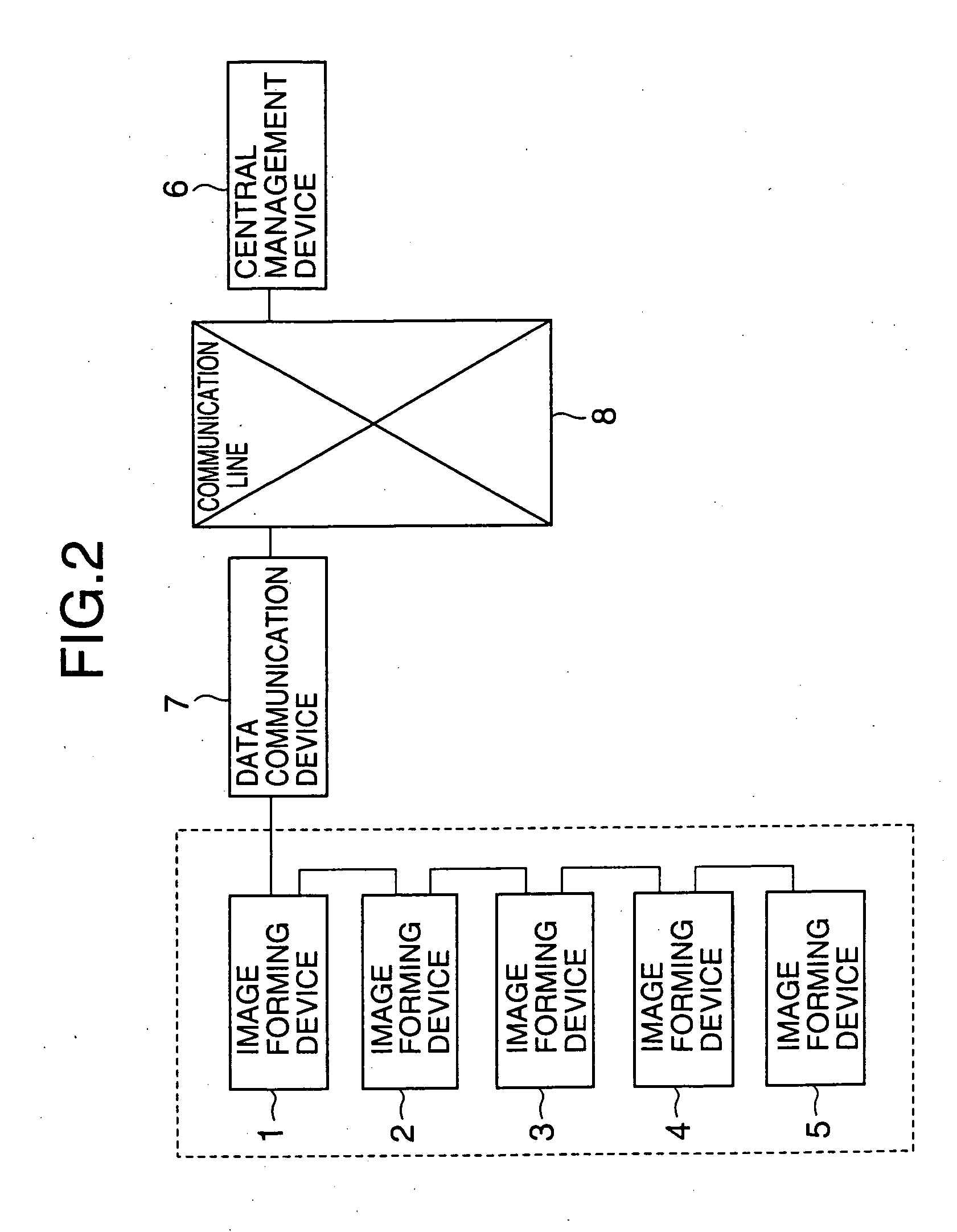
[0079] The image-forming-device management system includes image-forming devices 1 through 5, a central management device 6, a data communication device 7 and a communication line 8.

[0080] The image-forming devices 1 through 5 are remotely managed devices such as copy machines, and are connected to the data communication device 7 through a communication line. The data communication device 7 is connected to the central management device 6 through the communication line 8 such as a public line or an exclusive line. The central management device 6 can carry out remote management of the image-forming devices 1 through 5 collectively through the communication line 8 and the data communication device 7.

[0081] The data communication device 7 is connected to the communication line 8, and transmits an instruction signal received from the central management device 6 to the image-forming devices 1 through 5 selectively, or each type of report data received from the image-forming devices 1 th...

second embodiment

[0200]FIG. 20 is a block diagram showing a, structure of a control unit of each image-forming device 1 through 5 used in the image-forming-device management system according to the A unit shown in FIG. 20 corresponding to a unit shown in FIG. 3 has the same unit number as the unit shown in FIG. 3.

[0201] The control unit of each image-forming device 1 through 5 includes the PPC controller composed of the CPU 11, the RTC (Real-Time. Clock circuit) 12, the ROM 13, the RAM 14, the non-volatile RAM 15, the input / output port 16, and the serial communication control units 17a, 17b and 17c. The control unit further includes the personal interface 18, the system bus 19, a main power source 61, a sub power source 62 and a backup switch 63.

[0202] The CPU 11 is a central processing unit that controls the entire control unit collectively by using a control program stored in the ROM 13, and functions as power-supply part setting means. The real-time clock circuit (RTC) 12 functions as data-tran...

third embodiment

[0385] A description will now be given of a facsimile (FAX) compound device used in an image-forming-device management system according to the present invention.

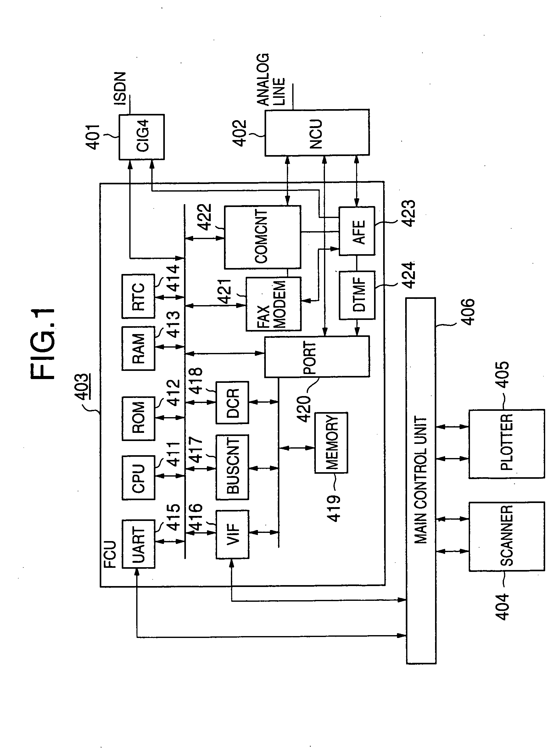
[0386]FIG. 37 is a block diagram showing a structure of a main unit of the facsimile compound device used in the image-forming-device management system according to the third embodiment. The facsimile compound device shown in FIG. 37 includes a CIG4 301, an NCU 302, an FCU 303, a printer controller 304, a scanner 305, a plotter 306, a personal interface (PI) 307, an LADP 308, a main control unit 309, a main power source 310, a sub power source 311 and a power-supply control unit 312. In addition, the facsimile compound device includes an operation display unit not shown in the figures.

[0387] The CIG 4301 is a G4 unit of a facsimile device, and is always supplied with electricity from the sub power source 311. The NCU 302 is a network control unit always supplied with the electricity from the sub power source 311, and carrie...


PUM


Abstract

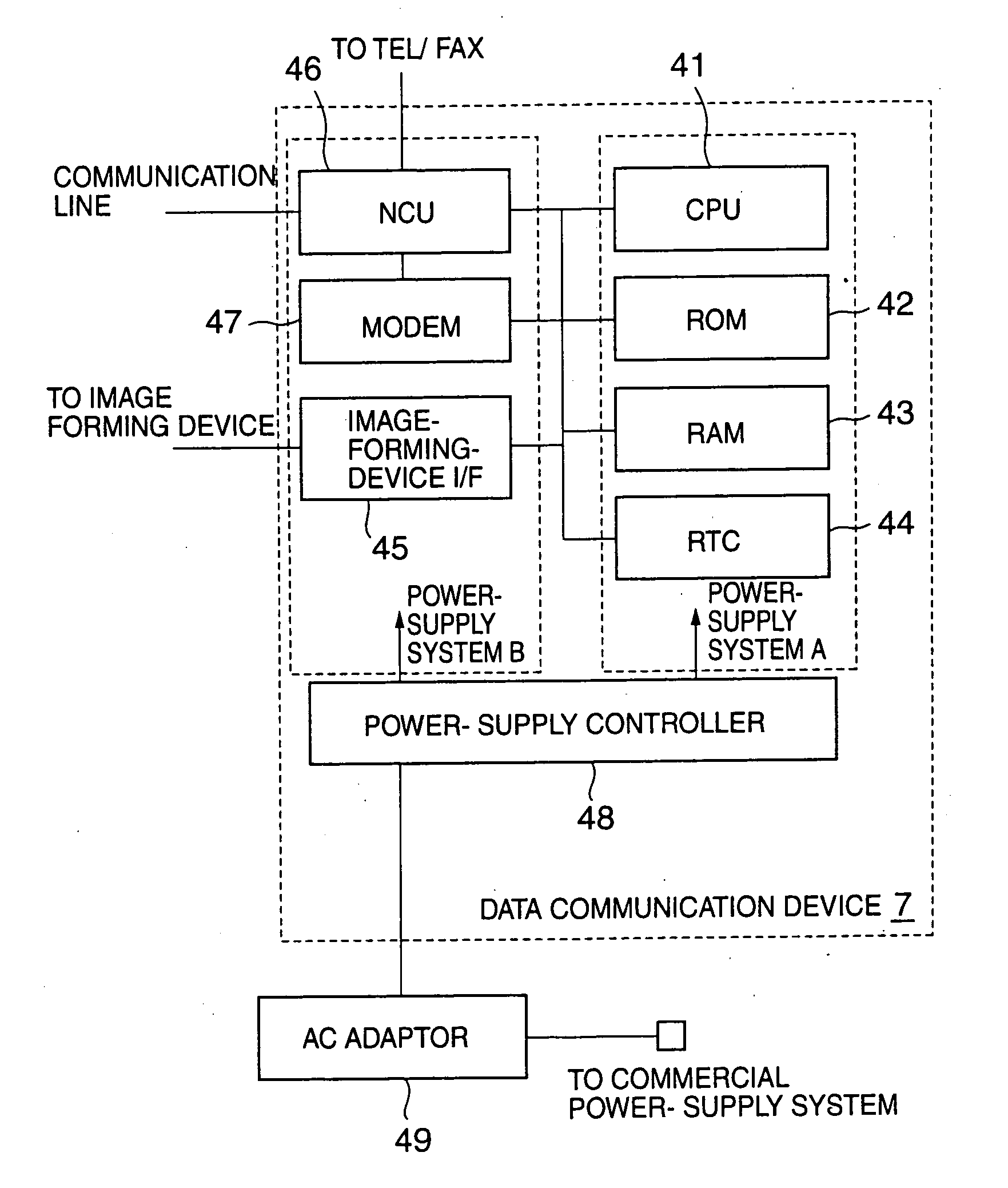
An image-forming-device management system includes an image-forming device, a data communication device and a central management device. A real-time clock circuit (RTC) of the data communication device compares a current time with a predetermined data transmission time. If the current time matches with the data transmission time, the RTC generates a data-transmission request that requests for data transmission to the central management device. A CPU included in a part constantly supplied with electricity from a power source in the data communication device instructs a power-source controller to supply the electricity from the power source to a communication-related part including a network control unit (NCU), a modem and an image-forming-device interface, thereby activating the communication-related part. Subsequently, the CPU calls out the central management device by using the NCU, and transmits data acquired from the image-forming device in advance, to the central management device by using the modem.

Description

BACKGROUND OF THE INVENTION [0001] 1. Field of the Invention [0002] The present invention relates to a data communication device, an image-forming device such as a copy machine or a facsimile composite device, an image-forming-device management system composed of the data communication device and the image-forming device, and a method of controlling power supply in the image-forming-device management system. [0003] 2. Description of the Related Art [0004] An image-forming-device management system enables each image-forming device installed in a large number of customer offices and the like to connect to a central management device installed in a service center by using a data communication device and a communication line such as a public line or an exclusive line. This image-forming device is defined as a copy machine, a printer, a facsimile device, or the like. Additionally, the central management device carries out remote management of the image-forming device through the communic...

Claims


Application Information

Patent Timeline
IPC IPC(8): G06F1/32G06F3/12H04N1/00B41J29/38H04N1/32
CPCH04N1/00885H04N1/00888H04N1/00896H04N2201/0082H04N1/32507H04N1/32523H04N2201/0081H04N1/32502
Inventor OGURA, MASAAKIWATANABE, HIDEHIKOSUZUKI, KOUBUN
Owner RICOH KK
Learn More