Method of signal transmission in a WDM communication system

Inactive Publication Date: 2005-08-18
WSOU INVESTMENTS LLC +1
View PDF8 Cites 0 Cited by
  • Summary
  • Abstract
  • Description
  • Claims
  • Application Information

AI Technical Summary

Benefits of technology

[0005] Problems in the prior art are addressed, in accordance with the principles of the present invention, by a method of signal transmission in a WDM communication system, according to which an optical transmitter is overdriven to produce a favorable phase shift between different optical bits. In a representative embodiment, a transmitter of a WDM communication system is equipped with a Mach-Zehnder modulator (MZM) configured to produce an optical signal corresponding to a duobinary data stream by modulating a beam of light passing through the MZM. A three-level electrical signal is applied to the MZM to modulate the light. At the second signal level, the modulator substantially blocks light transmission. At the first and third levels, the modulator transmits light corresponding to the duobinary “−1” and “+1” bits, respectively, such that a relative phase shift between the optical bits is different than 180 degrees, i.e., the phase shift value employed in prior-art optical duobinary modulation. Advantageously, by appropriately selecting voltages for the first and third levels, the relative phase shift between the optical bits can be adjusted to reduce detrimental effects of optical bandpass filtering typically present in the WDM communication system, thereby reducing the number of decoding errors at the receiver.
[0008] According to yet another embodiment, the present invention is a communication system, comprising an optical transmitter and an optical receiver coupled via a communication link, wherein: (i) the optical transmitter comprises: a modulator adapted to modulate an optical beam with data; and a driver adapted to drive the modulator with an electrical signal corresponding to the data; (ii) the communication link subjects the modulated beam to bandpass filtering; and (iii) the modulator is overdriven to introduce a phase shift between optical symbols in the modulated beam such that, at the receiver, inter-symbol interference caused by the bandpass filtering is reduced.

Problems solved by technology

However, this filtering also results in optical waveform distortion, which increases the number of decoding errors at the receiver.

Method used


Image

  • Method of signal transmission in a WDM communication system
  • Method of signal transmission in a WDM communication system
  • Method of signal transmission in a WDM communication system

Examples


Embodiment Construction

[0016] Reference herein to “one embodiment” or “an embodiment” means that a particular feature, structure, or characteristic described in connection with the embodiment can be included in at least one embodiment of the invention. The appearances of the phrase “in one embodiment” in various places in the specification are not necessarily all referring to the same embodiment, nor are separate or alternative embodiments mutually exclusive of other embodiments.

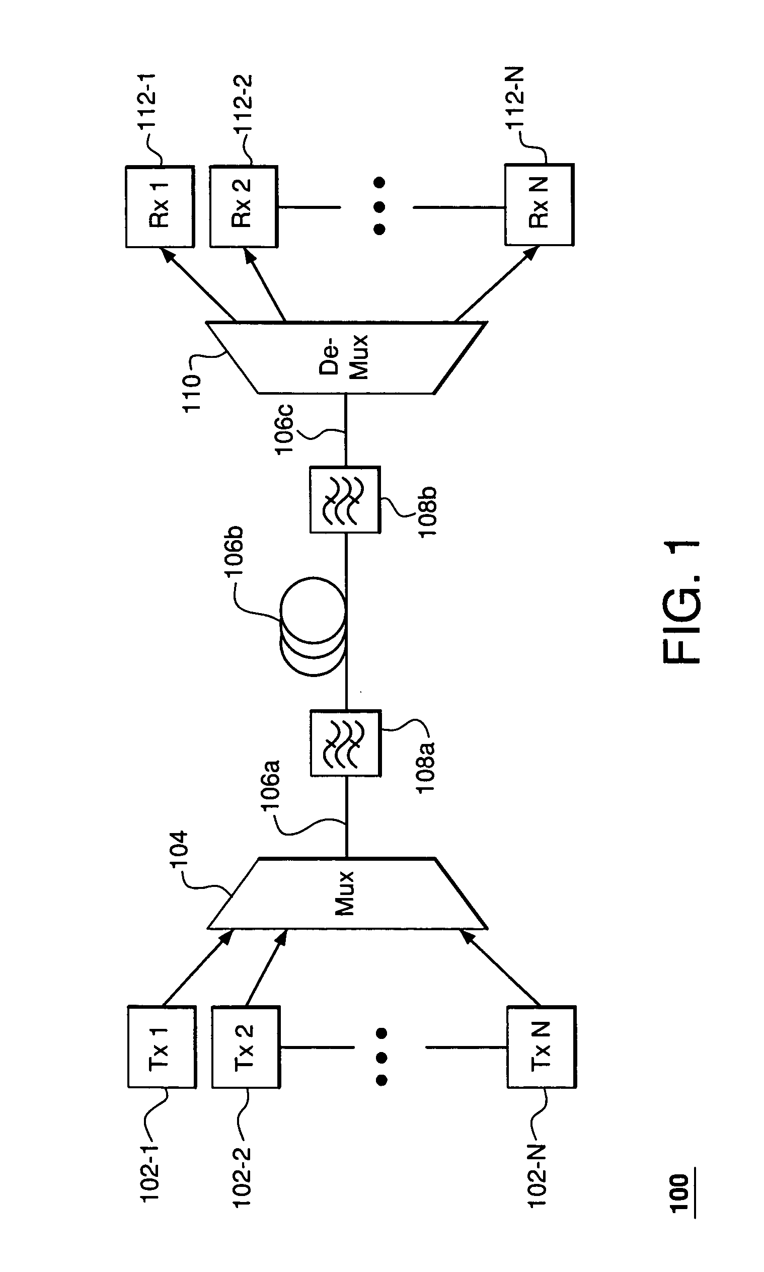
[0017]FIG. 1 shows a representative WDM communication system 100 in which the present invention may be practiced. System 100 has N optical transmitters 102-i (where i=1, 2, . . . N), each sending an optical signal corresponding to a WDM channel and operating at a designated wavelength. An optical multiplexer (MUX) 104 combines the outputs of transmitters 102-i into a multiplexed optical signal, which is then transmitted to optical de-multiplexer (De-MUX) 110 through spans of optical fiber 106 and optical bandpass filters 108 inte...


PUM


Abstract

In a representative embodiment, a transmitter of a WDM communication system is equipped with a Mach-Zehnder modulator (MZM) configured to produce an optical signal corresponding to a duobinary data stream by modulating a beam of light passing through the MZM. A three-level electrical signal is applied to the MZM to modulate the light. At the second signal level, the modulator substantially blocks light transmission. At the first and third levels, the modulator transmits light corresponding to the duobinary “−1” and “+1” bits, respectively, such that a relative phase shift between the optical bits is different than 180 degrees, i.e., the phase shift value employed in prior-art optical duobinary modulation. Advantageously, by appropriately selecting voltages for the first and third levels, the relative phase shift between the optical bits can be adjusted to reduce detrimental effects of optical bandpass filtering typically present in the WDM communication system, thereby reducing the number of decoding errors at the receiver.

Description

BACKGROUND OF THE INVENTION [0001] 1. Field of the Invention [0002] The present invention relates to optical communication equipment and, more specifically, to equipment for WDM communication systems. [0003] 2. Description of the Related Art [0004] To achieve high transmission capacity, wavelength-division multiplexing (WDM) communication systems should have relatively high spectral efficiency. For example, to achieve a capacity of 1.2 Tbit / s, a WDM system operating over a wavelength range of about 25 nm (3.1 THz) should have a spectral efficiency of about 0.4 bit / s / Hz. This corresponds to a channel spacing of about 0.8 nm (100 GHz) for a bit rate of 40 Gbit / s. With WDM channel packing this dense, narrow bandpass filtering should be employed to provide good channel isolation / crosstalk reduction. However, this filtering also results in optical waveform distortion, which increases the number of decoding errors at the receiver. It is therefore desirable to have a method of signal trans...

Claims


Application Information

Patent Timeline
IPC IPC(8): H04B10/06H04B10/04H04B10/142H04B10/152H04B10/155H04B10/18H04J14/00H04J14/02
CPCH04B10/25137H04B10/508H04B10/505
Inventor DUELK, MARCUS
Owner WSOU INVESTMENTS LLC
Why Eureka
Try Eureka