Microfibrous fuel cell assemblies comprising fiber-supported electrocatalyst layers, and methods of making same

a fuel cell and microfibrous technology, applied in the field of fuel cell assemblies, can solve the problems of affecting the mea structure and long-term performance of the fuel cell, and the membrane contraction may have a deleterious effect on the fuel cell long-term performance, and achieve the effect of facilitating the conformation of such fiber networks and minimizing damage to individual fibers

Active Publication Date: 2005-08-18
MICROCELL CORP
View PDF25 Cites 28 Cited by
  • Summary
  • Abstract
  • Description
  • Claims
  • Application Information

AI Technical Summary

Benefits of technology

[0022] The electrocatalyst structure (i.e., the inner and / or outer electrocatalyst layer) of the present invention is preferably substantially free of fibers that are orthogonally oriented in relation to the longitudinal axis of the microfibrous fuel cell element, and more preferably, it is substantially free of fibers that are not parallelly oriented in relation to the longitudinal axis of such fuel cell. Instead, essentially all the fibers incorporated in the supporting fiber network of such electrocatalyst structure are unidirectional, i.e., they are parallelly oriented or substantially parallel in relation to the longitudinal axis of the microfibrous fuel cell, which facilitates conformation of such fiber network to the microfibrous contour of the fuel cell structure and minimizes damage to individual fibers caused by overbending or overstressing.

Problems solved by technology

The expansion and contraction of the membrane may have a deleterious effect on the MEA structure and long-term performance of the fuel cell.

Method used


Image

  • Microfibrous fuel cell assemblies comprising fiber-supported electrocatalyst layers, and methods of making same
  • Microfibrous fuel cell assemblies comprising fiber-supported electrocatalyst layers, and methods of making same
  • Microfibrous fuel cell assemblies comprising fiber-supported electrocatalyst layers, and methods of making same

Examples


example 1

[0142] This example shows the procedure for preparing a single microfibrous fuel cell with carbon fiber-supported electrocatalyst layer, using a binding solution that contains Nafion® and a removable carrier Y2O3:

[0143] The processing steps were as follows:

[0144] First, a membrane-electrode-assembly (MEA) containing the inner electrocatalyst layer and the membrane separator layer was formed according to the continuous extrusion process disclosed in U.S. patent application Ser. No. 10 / 744,203. The extrusion system was comprised of the following equipment: [0145] Let-off stand for the current collector wire spool [0146] Single-layer extrusion die for applying platinum ink to the wire [0147] Piston pump for dispensing Pt ink catalyst [0148] Single-layer extrusion die for applying Nafion® solution to the wire [0149] Piston pump for dispensing Nafion® membrane-forming solution [0150] Two medium wave infrared (IR) dryers—each 1 meter long [0151] Belted pulling unit to move the wire thro...

example 2

[0170] This example illustrates the testing results of a sub-bundle formed of multiple microfibrous fuel cells with carbon fiber-supported electrocatalyst layer as fabricated in Example 1.

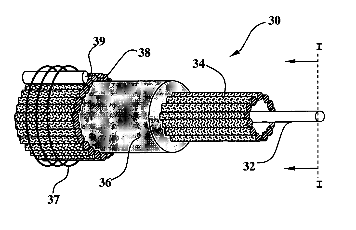
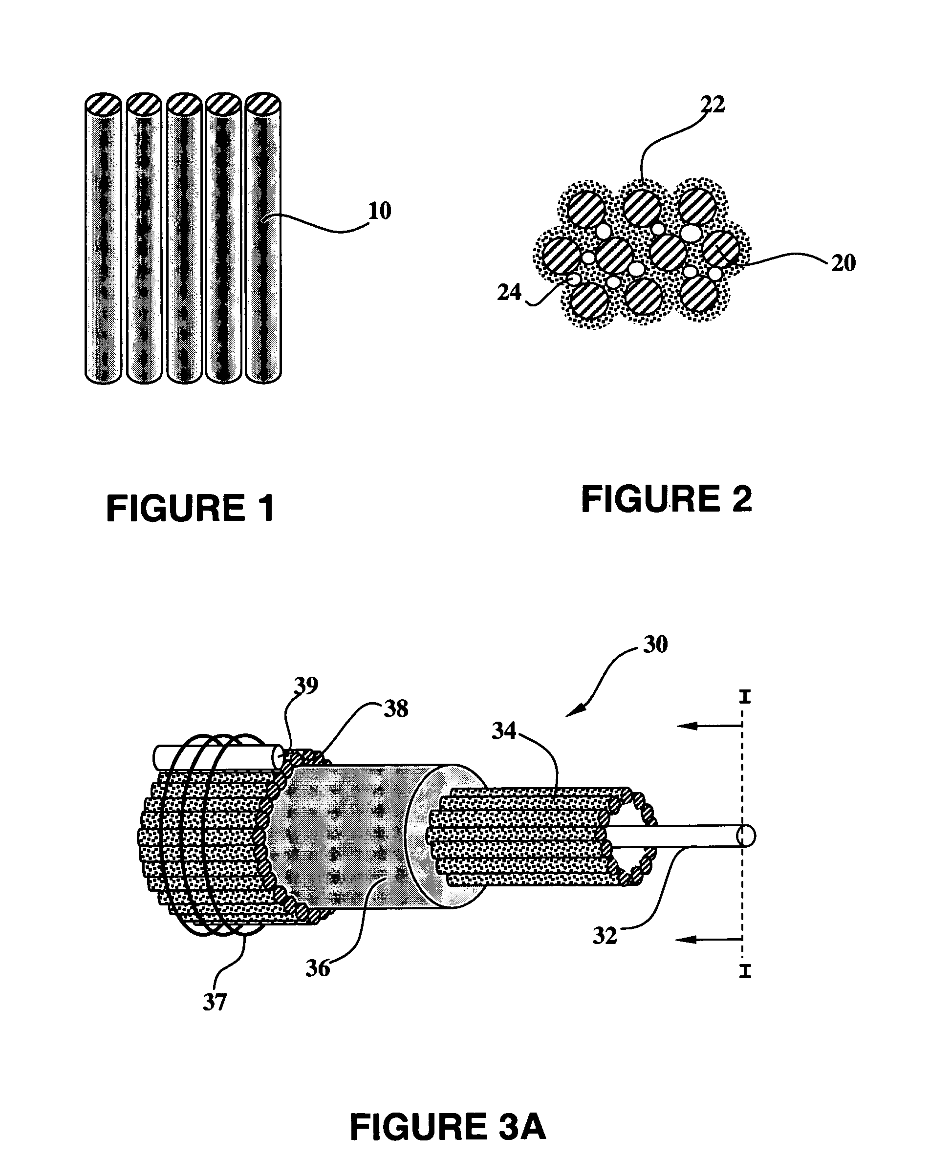
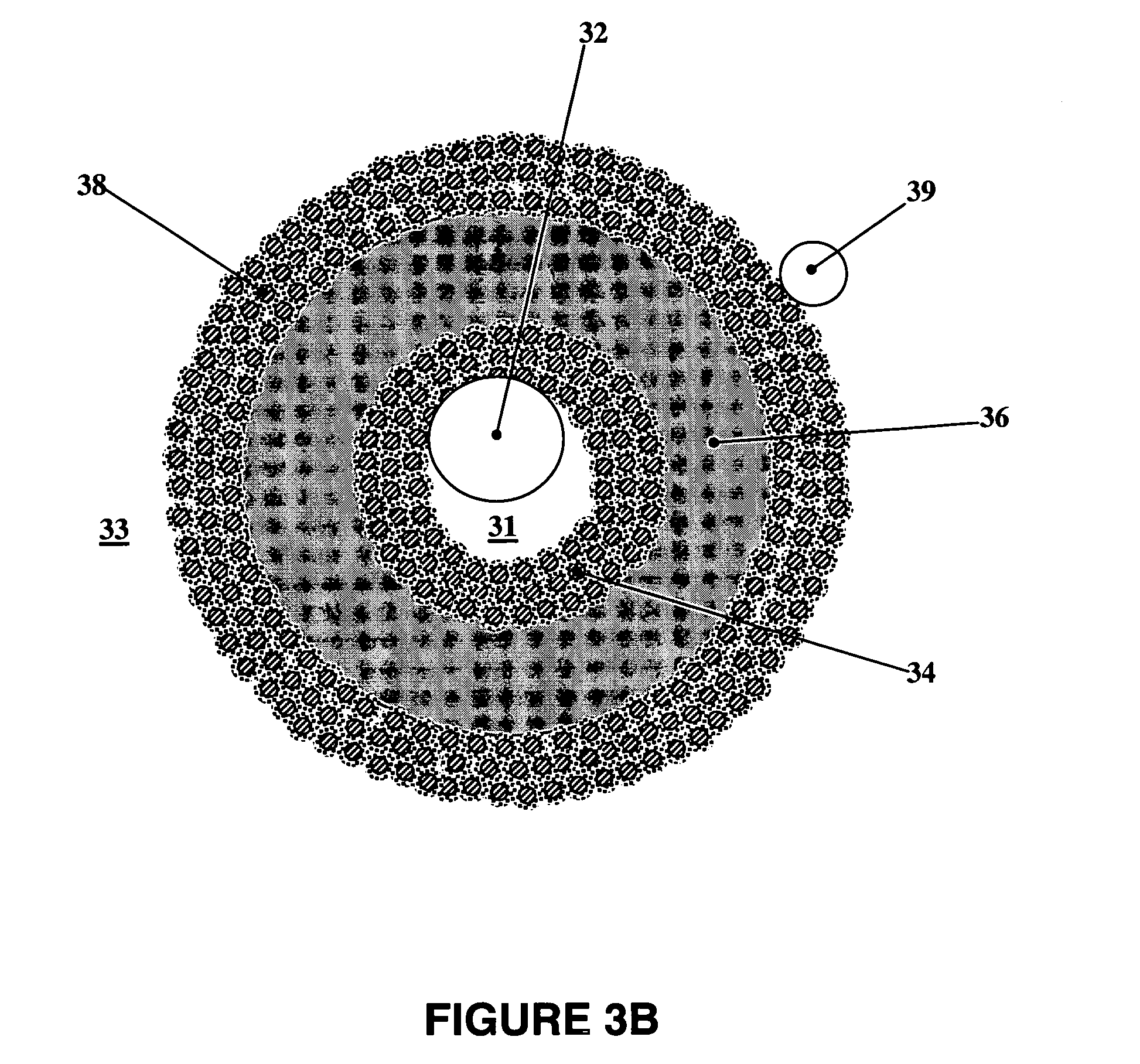
[0171] Eleven microfibrous fuel cells were bundled together around a ⅛″ (OD) carbon tube and potted into a sub-bundle. The microfibrous fuel cells were uniformly arranged in a parallel configuration around the carbon tube, which was used as a heat exchange tube. Details of the heat exchange system as used in this example were disclosed in U.S. patent application Ser. No. 10 / 794,687 as filed Mar. 5, 2004, the content of which is incorporated herein by reference in its entirety. The fuel cells were connected in parallel with one another, i.e. outer current collector of each cell was connected together to form one terminal and inner current collector of each cell was connected together to form another terminal.

[0172] The active cathode surface area of the sub-bundle was about 32 cm2. Air was passed ...

example 3

[0177] Example 3 shows the performance of another sub-bundle made of the microfibrous fuel cells with carbon fiber-supported electrocatalyst layer as fabricated in Example 1.

[0178] All parameters were the same as those in Examples 1 and 2, except: [0179] Flow rate (or recirculation rate) for H2: 25 (mL / min) / A;—No humidification [0180] Flow rate for Air: 30 (mL / min) / A;—No humidification

[0181]FIG. 13 shows the polarization curve of such sub-bundle.


PUM

PropertyMeasurementUnit
diameteraaaaaaaaaa
tensile strengthaaaaaaaaaa
thermal conductivityaaaaaaaaaa

Abstract

The present invention relates to a microfibrous fuel cell structure of elongated form with a longitudinal axis. Such microfibrous fuel cell comprises electrocatalyst layers supported by a fiber network formed of unidirectional or substantially unidirectional conductive fibers. The conductive fibers of such fiber network are oriented parallelly or substantially parallelly to the longitudinal axis of the fuel cell, therefore allowing such fiber network to conform to the curvature of the microfibrous fuel cell along the radial direction but without causing overbending of the individual fibers.

Description

CROSS-REFERENCE TO RELATED APPLICATIONS [0001] This claims priority to U.S. Provisional Patent Application No. 60 / 544,729, filed Feb. 13, 2004 in the names of Ray R. Eshraghi, Changquig Lin, Jung-Chou Lin, and Martin E. Ketterer for “MICROFIBROUS FUEL CELL ASSEMBLIES COMPRISING FIBER-SUPPORTED ELECTROCATALYST LAYERS, AND METHODS OF MAKING SAME.”GOVERNMENT INTEREST [0002] The U.S. government may own rights in the present invention, pursuant to Grant No. 70NANB1H3039 awarded by the Advanced Technology Program (ATP) of National Institute of Science and Technology (NIST).BACKGROUND OF THE INVENTION [0003] 1. Field of the Invention [0004] The present invention relates to fuel cell assemblies comprising one or more microfibrous fuel cell elements containing fiber-supported electrocatalyst layers, and methods of making same. [0005] 2. Description of the Related Art [0006] The recently developed microfibrous electrochemical cells, as disclosed by Ray R. Eshraghi in U.S. Pat. Nos. 5,916,514;...

Claims


Application Information

Patent Timeline
Patent Type & Authority Applications(United States)
IPC IPC(8): H01M4/86H01M4/88H01M4/92H01M4/96H01M8/02H01M8/04H01M8/10H01M8/24
CPCH01M4/8605Y02E60/522H01M4/8807H01M4/8817H01M4/8846H01M4/92H01M4/921H01M4/928H01M8/004H01M8/0234H01M8/0247H01M8/0252H01M8/0278H01M8/04089H01M8/1004H01M8/1023H01M8/1027H01M8/1032H01M8/1039H01M8/1044H01M8/106H01M8/1062H01M8/243H01M2250/30Y02B90/18H01M4/8626H01M8/241Y02B90/10Y02E60/50H01M8/2418
Inventor ESHRAGHI, RAY R.LIN, CHANGQINGLIN, JUNG-CHOUKETTERER, MARTIN E.
Owner MICROCELL CORP
Why Eureka
Try Eureka