Display panel, control display panel and method for integrally molding insert material

a technology of display panel and insert material, which is applied in the direction of display means, visual presentation, advertising, etc., can solve the problems of complex operation, high cost, and complicated display panel itself, and achieve the effect of hardly molded stably and stably molded into a desired configuration

Active Publication Date: 2005-08-25
PANASONIC CORP
View PDF3 Cites 17 Cited by
  • Summary
  • Abstract
  • Description
  • Claims
  • Application Information

AI Technical Summary

Benefits of technology

[0075] According to the insert molding method of the present invention, problems such that the sheet is peeled off and warped and is hardly molded stably into a desired c...

Problems solved by technology

However, accompanying the multifunction tendency in electronic apparatuses, the simpler configuration leads to a more complicated operation.
Contrarily, to simplify the operation, when various switches such as a menu key and setting key are disposed in the display panel, a disadvantage that the configuration of the display panel itself becomes complicated results in a high cost.
However, in a process in which the above-mentioned front printed sheet and the rear printed sheet are adhered to the panel base body of a transparent resin or the like using an adhesive, a double-sided adhesive tape or the like, the adhered face between the rear printed sheet and the panel base body is seen from the front side resulting in an undesirable state in appearance.
Also, the display panel is illuminated by a light source such as an LED from the rear face side, occasionally, uneven display and/or incorrect display due to leaked light are seen from the front side surface of the display panel.
This is caused by the fact that, if there is any gap between the rear printed sheet and panel base body, the light readily leaks therefrom.
However, when the a...

Method used


Image

  • Display panel, control display panel and method for integrally molding insert material
  • Display panel, control display panel and method for integrally molding insert material
  • Display panel, control display panel and method for integrally molding insert material

Examples


first embodiment

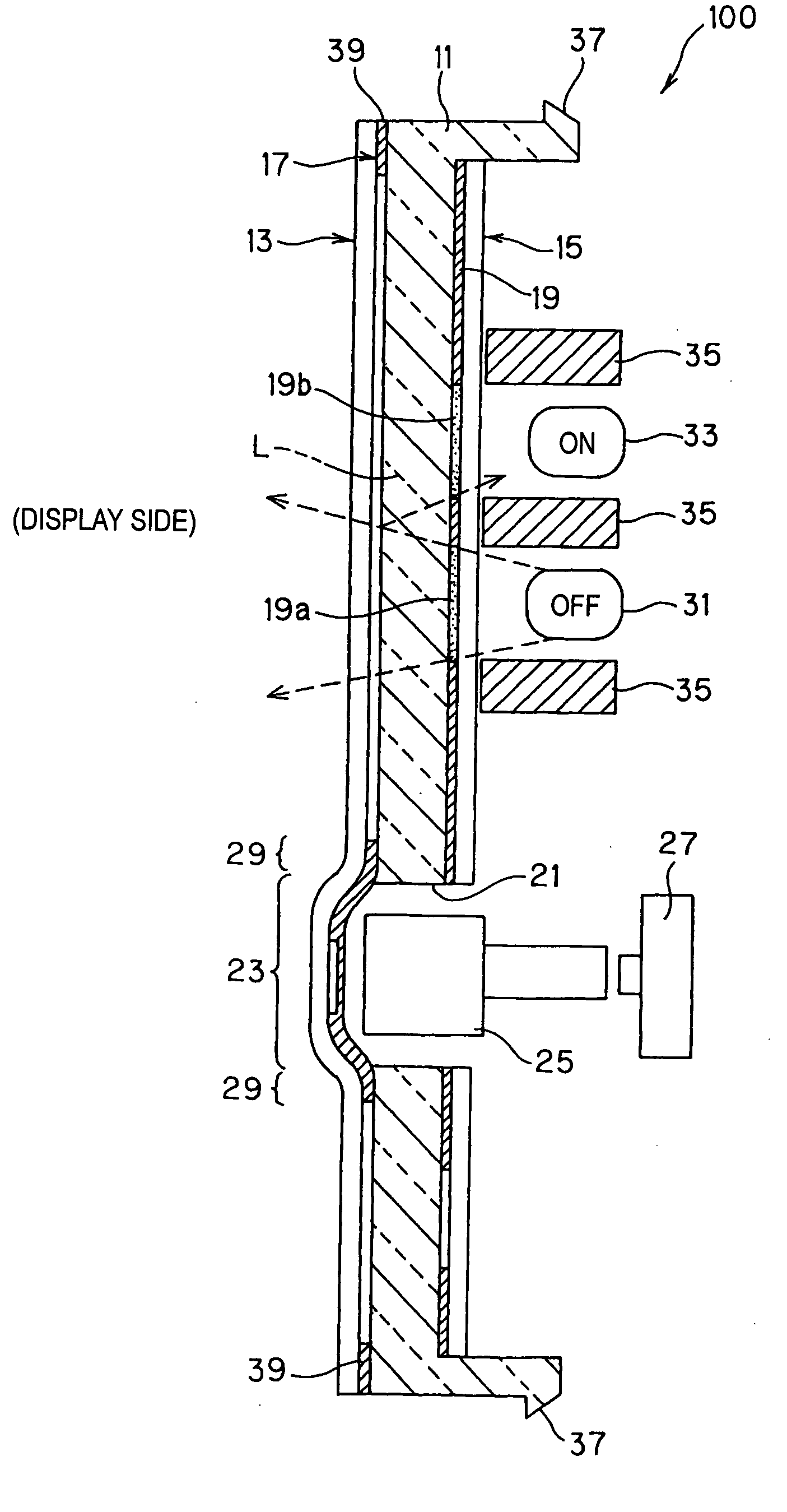
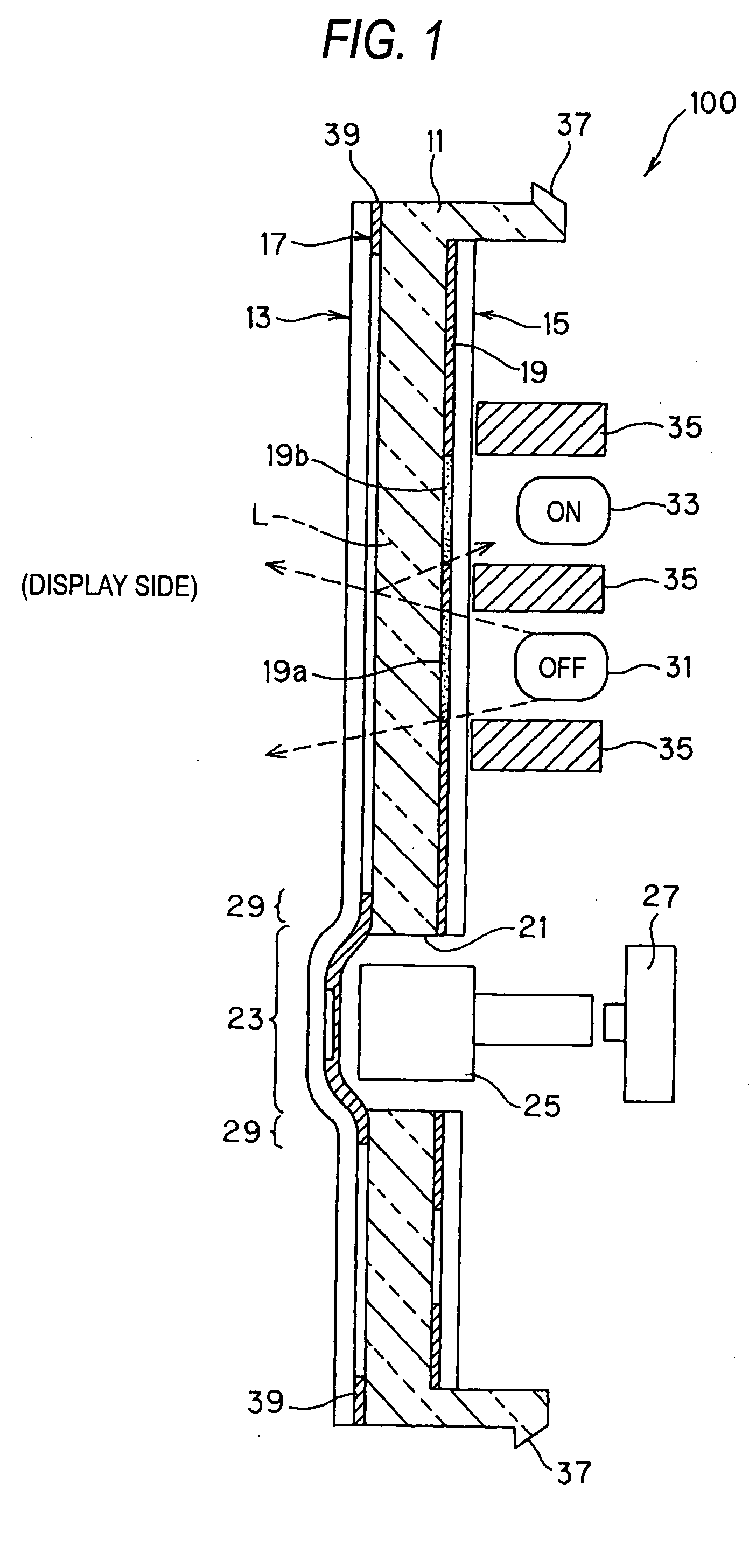
[0115]FIG. 1 is a schematic sectional view of a structure for illustrating the characteristics of a display panel according to the present invention.

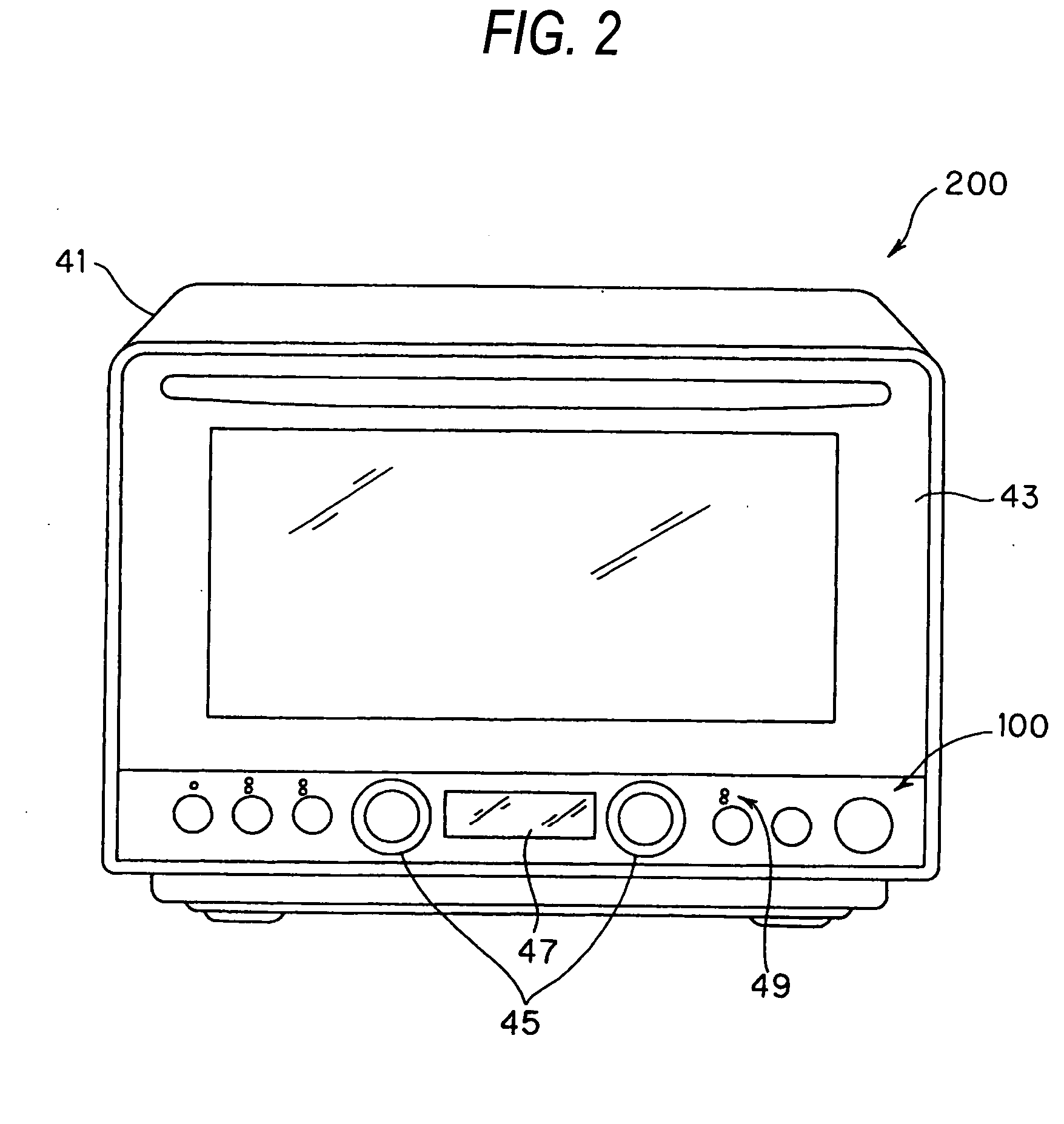
[0116] A display panel 100 is mounted on an electronic apparatus. The display panel 100 mainly includes a panel base body 11 formed of a translucent material such as transparent resin, a printed sheet (referred to as front sheet) 13 which serves as a first printed display layer adhered to the front side surface of the panel base body 11 and a printed sheet (referred to as rear sheet) 15 which serves as a second printed display layer adhered to the rear side surface thereof. The display panel 100 is an insert-molded article, in which the front sheet 13 and the rear sheet 15 are integrally molded being opposed to each other with the panel base body 11 sandwiched therebetween.

[0117] The front sheet 13 is a sheet having a transparent tone, which is printed on a part of a translucent base, and is integrally formed with a printed layer 17 di...

second embodiment

[0185]FIG. 19 is a sectional view illustrating an insert molding method of a second embodiment according to a present invention. FIGS. 20A to 20E illustrate a molding procedure for the insert molding method shown in FIG. 19. FIG. 21 is a schematic view of a gate and the periphery thereof in the insert molding method shown in FIG. 19. FIG. 22 is an external view of the gate and the periphery thereof for the first half of the insert molding method shown in FIG. 19. FIG. 23 is an external view of the gate and the periphery thereof for the second half of the insert molding method shown in FIG. 19.

[0186] As shown in FIG. 19, the insert molding method as the second embodiment of the present invention uses a molding machine 10 including an upper die 11 and a lower die 12. A sheet 14 is disposed on the lower die 12 side in a cavity 13 formed by the upper die 11 and the lower die 12.

[0187] A concave portion 15 is formed in the upper die 11, and a convex portion 16 disposed so as to face to ...

third embodiment

[0202] As shown in FIG. 24, the insert molding method uses a molding machine 30 equipped with an upper die 31 and a lower die 32. A rear sheet 34 is disposed on the lower die 32 side in the cavity 33 formed by the upper die 31 and the lower die 32; and a front sheet 35 is disposed on the upper die 31 side in the cavity 33.

[0203] In the upper die 31, a spherical concave portion 37 having a semispherical shape is formed in the central area of the concave portion 36; and in the lower die 32, a spherical convex portion 39 having a semispherical shape, which is disposed facing the spherical concave portion 37, is formed in the central area of the convex portion 38. And between the end portion of the upper die 31 and the end portion of the lower die 32, a gate 40 for filling a resin material is formed. The gate 40 is disposed above the extended portion 41 of the rear sheet 34.

[0204] The rear sheet 34 is a plate member of a transparent or semi-transparent resin; in the spherical convex p...


PUM


Abstract

A display panel which is adapted to be mounted on an electronic apparatus, includes a first printed display layer, a transparent material layer that is provided on the first printed display layer, and a second printed display layer that is provided on the transparent material layer so as to correspond to the first printed display layer. The first printed display layer, the transparent material layer and the second printed display layer are integrally formed to each other. The second printed display layer is displayed from the first printed display layer side through the transparent material layer.

Description

BACKGROUND OF THE INVENTION [0001] The present invention relates to a display panel, a control display panel and an insert molding method for integrally molding an insert material such as sheet. [0002] Recently, from home electric appliances such as microwave ovens and rice cookers to information equipment such as mobile phones, in the display section of an electronic apparatus, a display panel in which film and resin material are integrally molded is widely used. Some panels are mounted with the switching function section, which is called a membrane switch (sheet switch). [0003] In order to simplify the operation procedures of an electronic apparatus, it is desired that the display panel have a simple configuration. However, accompanying the multifunction tendency in electronic apparatuses, the simpler configuration leads to a more complicated operation. Contrarily, to simplify the operation, when various switches such as a menu key and setting key are disposed in the display panel...

Claims


Application Information

Patent Timeline
IPC IPC(8): G09F13/04G09F19/00
CPCG09F13/04Y10S345/905
Inventor HIRATA, JUNJIHAYAKAWA, YUJITSUKAGUCHI, AKIHIROINADA, IKUHIROMATSUDA, MASATOGOTO, YOSHIHIDEMATSUOKA, KIYOMIGOTO, KAORU
Owner PANASONIC CORP
Why Eureka
Try Eureka