
Emission control valve having improved force-balance and Anti-coking

a technology of anti-coking and force-balancing, which is applied in the direction of mechanical equipment, machines/engines, and non-fuel substance addition to fuel, etc., can solve the problems of harsh operating environment of egr valves, detrimental to valve performance, and tailpipe emission requirements impose stringent control requirements on such valves, so as to minimize the influence of exhaust pressure fluctuations on valve operation, improve valve performance, and prolong useful life

Inactive Publication Date: 2005-08-25
SIEMENS VDO AUTOMOTIVE INC
View PDF6 Cites 0 Cited by
  • Summary
  • Abstract
  • Description
  • Claims
  • Application Information

AI Technical Summary

Benefits of technology

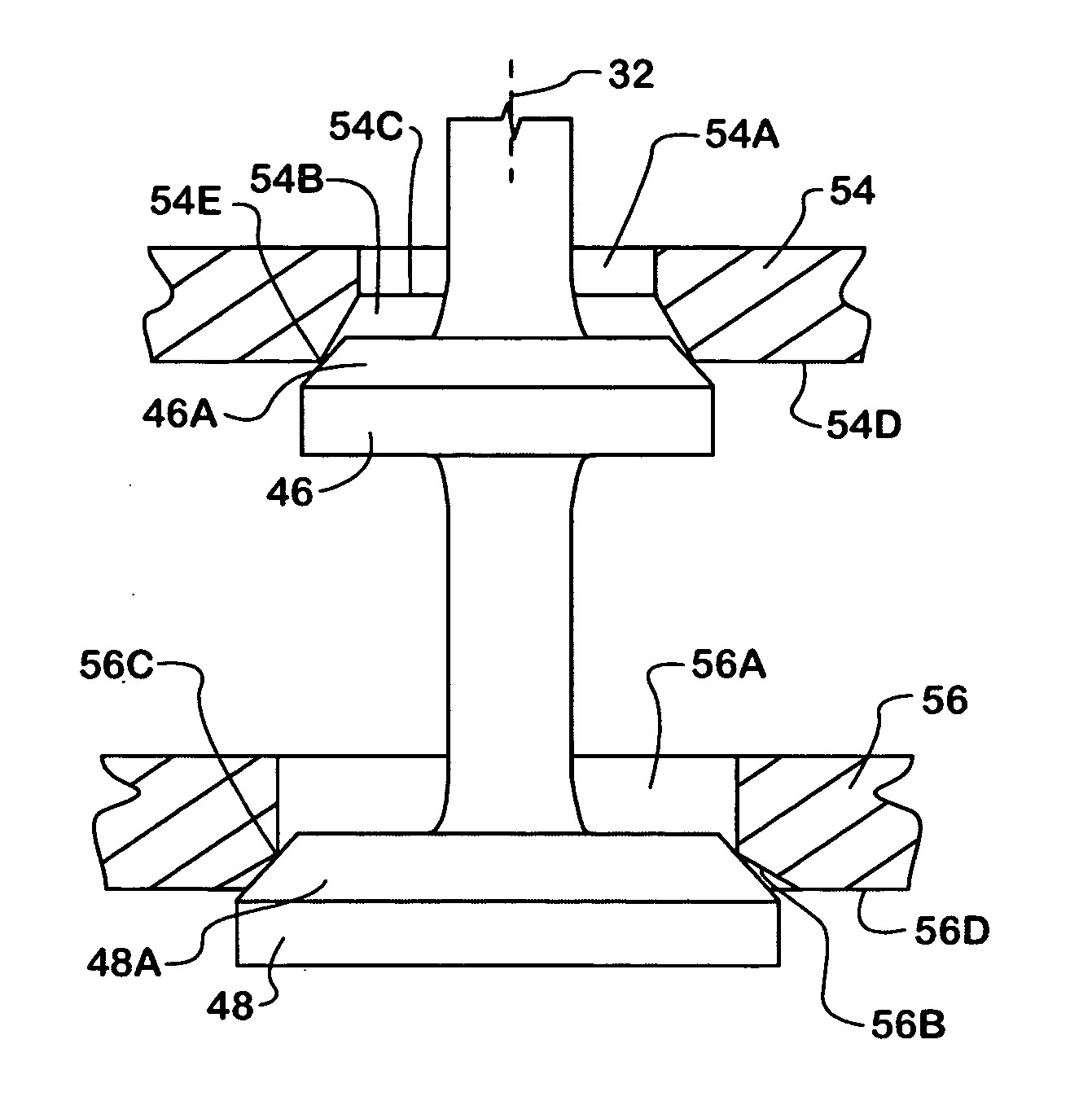
[0012] One improvement is directed to an interface that tends to discourage the deposit of materials from the exhaust gases passing through the valve on surfaces at the interface so that proper performance of an EEGR valve can continue during its useful life free of deposits at the interface that might otherwise seriously impair acceptable valve performance.
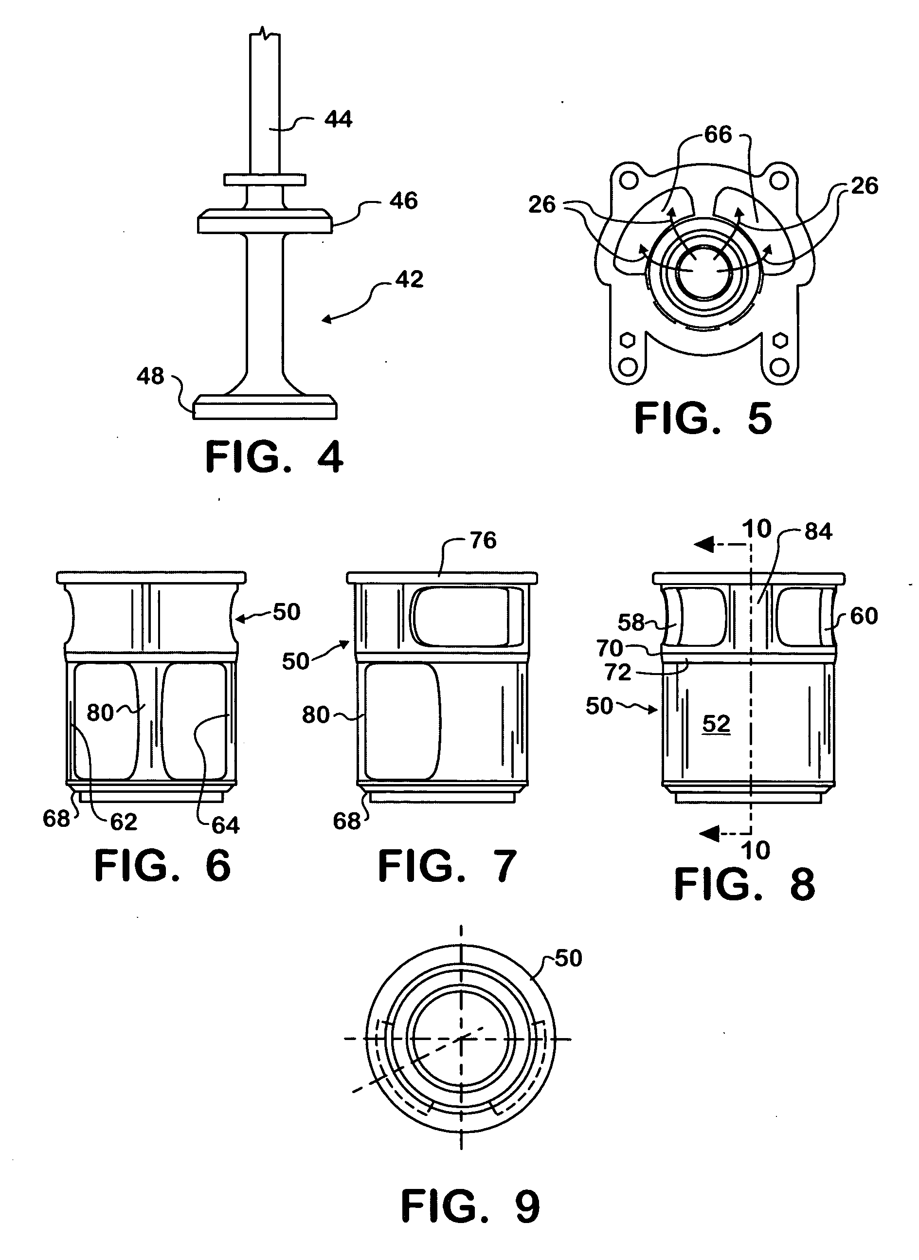
[0013] Another improvement is directed to better force-balancing of the pintle in a double-pintle EEGR valve for minimizing the influence of exhaust pressure fluctuations on valve operation. The conjunction of these improvements in an EEGR valve can contribute to better valve performance and longer useful life of an EEGR valve in an exhaust emission control system of a diesel engine, and with cost-effectiveness.

Problems solved by technology

Because they are typically engine-mounted, EGR valves are subject to harsh operating environments that include wide temperature extremes and vibrations.
Tailpipe emission requirements impose stringent demands on the control of such valves.
This phenomenon is sometimes called “coking”, and it can be detrimental to valve performance.
The nature of the deposited material may cause a pintle to stick to some extent on the seat when the pintle is closed, and that can interfere with proper valve operation.
For example, when the valve is to re-open, sticking may require extra force to unseat the pintle, particularly when the valve is cold.
The presence of such material can also interfere with proper pintle re-seating on the seat, possibly resulting in leakage through the valve when the pintle should seat fully closed on the seat.
However, the degree of sharpness of such a corner may complicate the process of making the part containing the edge.
Such an edge may be prone to nicking, also undesirable.

Method used


Image

  • Emission control valve having improved force-balance and Anti-coking
  • Emission control valve having improved force-balance and Anti-coking
  • Emission control valve having improved force-balance and Anti-coking

Examples


Embodiment Construction

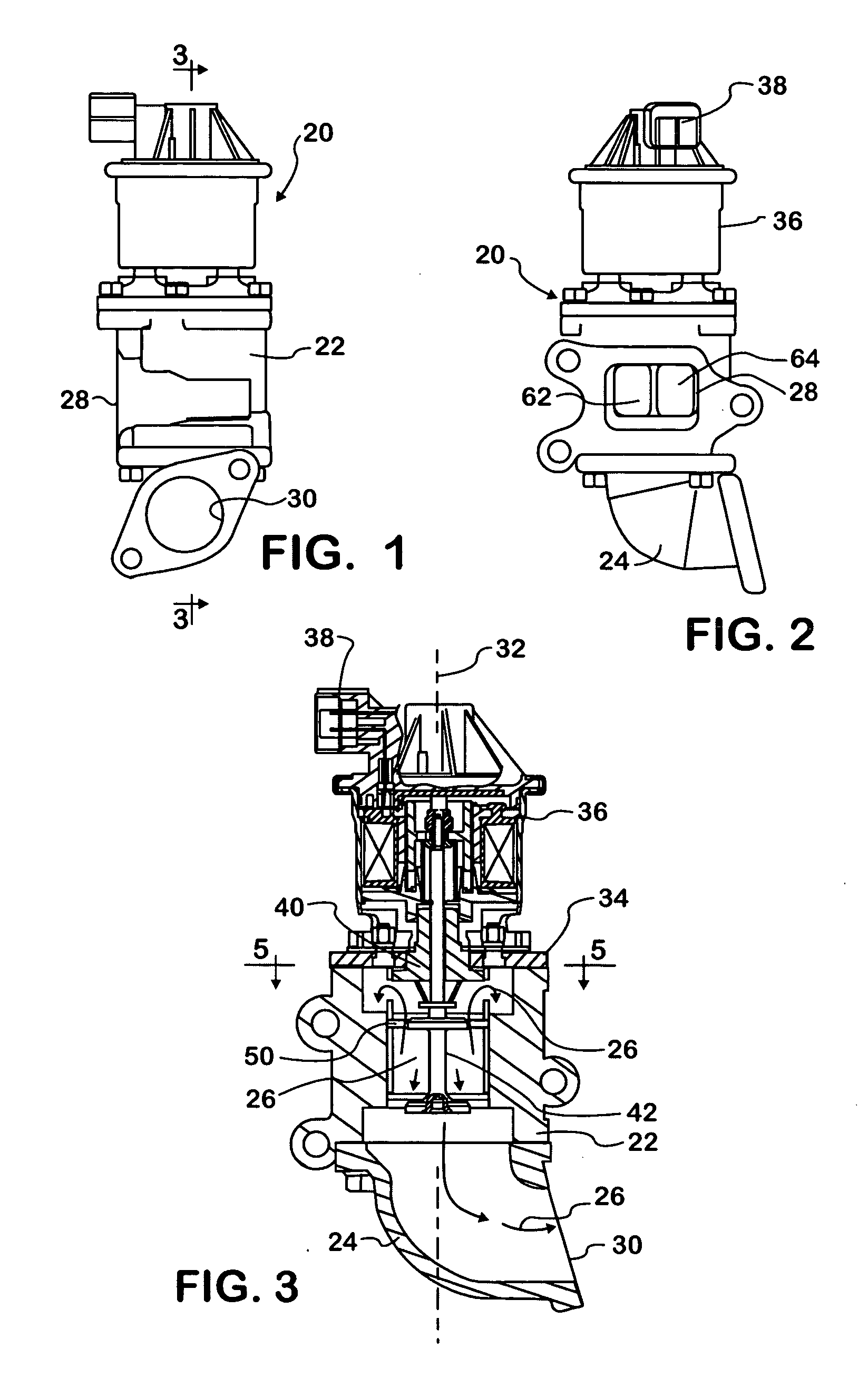
[0030]FIGS. 1-3 illustrate the general arrangement and organization of an exemplary EEGR valve 20 embodying principles of the present invention. Valve 20 comprises a base 22 and an elbow 24 assembled together to form a flow path 26 through the valve between an inlet port 28 provided in a flange at a side of base 22 and an outlet port 30 provided in a flange at one end of elbow 24.

[0031] Base 22 is a metal part that has a main longitudinal axis 32. Base 22 may be considered to have a generally cylindrical shape about axis 32 comprising a generally cylindrical wall bounding an interior space that is open at opposite axial end faces of the base. Base 22 is constructed so that its interior space is also open to inlet port 28.

[0032] An end of elbow 24 that is opposite the end containing outlet port 30 is fastened in a sealed manner to the lower end face of base 22 so that the interior of elbow 24 is open to the interior space of base 22. A cover 34 is fastened in a sealed manner to the...


PUM


Abstract

A double-pintle valve (20) has two seats (54, 56) each circumscribing a respective through-hole for exhaust gas flow. The through-hole of one seat (56) is large enough diametrically to allow the closure (46) that seats on the other seat (54) to pass through during fabrication of the valve. The closure (46) seats substantially on a radially outermost portion of a frustoconical surface zone (54B) of the seat (54) and the other closure (48) seats substantially on a radially innermost portion of a frustoconical surface zone (56B) of the one seat (56) when the valve is disallowing flow.

Description

FIELD OF THE INVENTION [0001] This invention relates generally to emission control valves that are used in emission control systems associated with internal combustion engines in automotive vehicles. The invention particularly relates to force-balance and anti-coking improvements in exhaust gas recirculation (EGR) valves. BACKGROUND OF THE INVENTION [0002] Controlled engine exhaust gas recirculation is a known technique for reducing oxides of nitrogen in products of combustion that are exhausted from an internal combustion engine to atmosphere. A typical EGR system comprises an EGR valve that is controlled in accordance with engine operating conditions to regulate the amount of engine exhaust gas that is recirculated to the fuel-air flow entering the engine for combustion so as to limit the combustion temperature and hence reduce the formation of oxides of nitrogen. [0003] Because they are typically engine-mounted, EGR valves are subject to harsh operating environments that include ...

Claims


Application Information

Patent Timeline
Patent Type & Authority Applications(United States)
IPC IPC(8): F02M25/07
CPCF02M25/0714F02M25/0744F02M25/0746Y02T10/121F02M25/0789F02M25/0792F02M25/0772F02M26/40F02M26/69F02M26/11F02M26/38F02M26/53F02M26/67
Inventor HRYTZAK, BERNARD J.
Owner SIEMENS VDO AUTOMOTIVE INC
Learn More