Object detecting apparatus and manufacturing method therefor

Inactive Publication Date: 2005-08-25
DENSO CORP
View PDF9 Cites 1 Cited by
  • Summary
  • Abstract
  • Description
  • Claims
  • Application Information

AI Technical Summary

Benefits of technology

[0009] It is therefore an object of the present invention to provide an object detecting apparatus and a manufacturing method therefor, which simplifies the apparatus and the method.

Problems solved by technology

The conventional apparatus thus requires the optical axis adjustment of the Fresnel lens J1, resulting in an increased and complication of the assembling process.

Method used


Image

  • Object detecting apparatus and manufacturing method therefor
  • Object detecting apparatus and manufacturing method therefor
  • Object detecting apparatus and manufacturing method therefor

Examples


Embodiment Construction

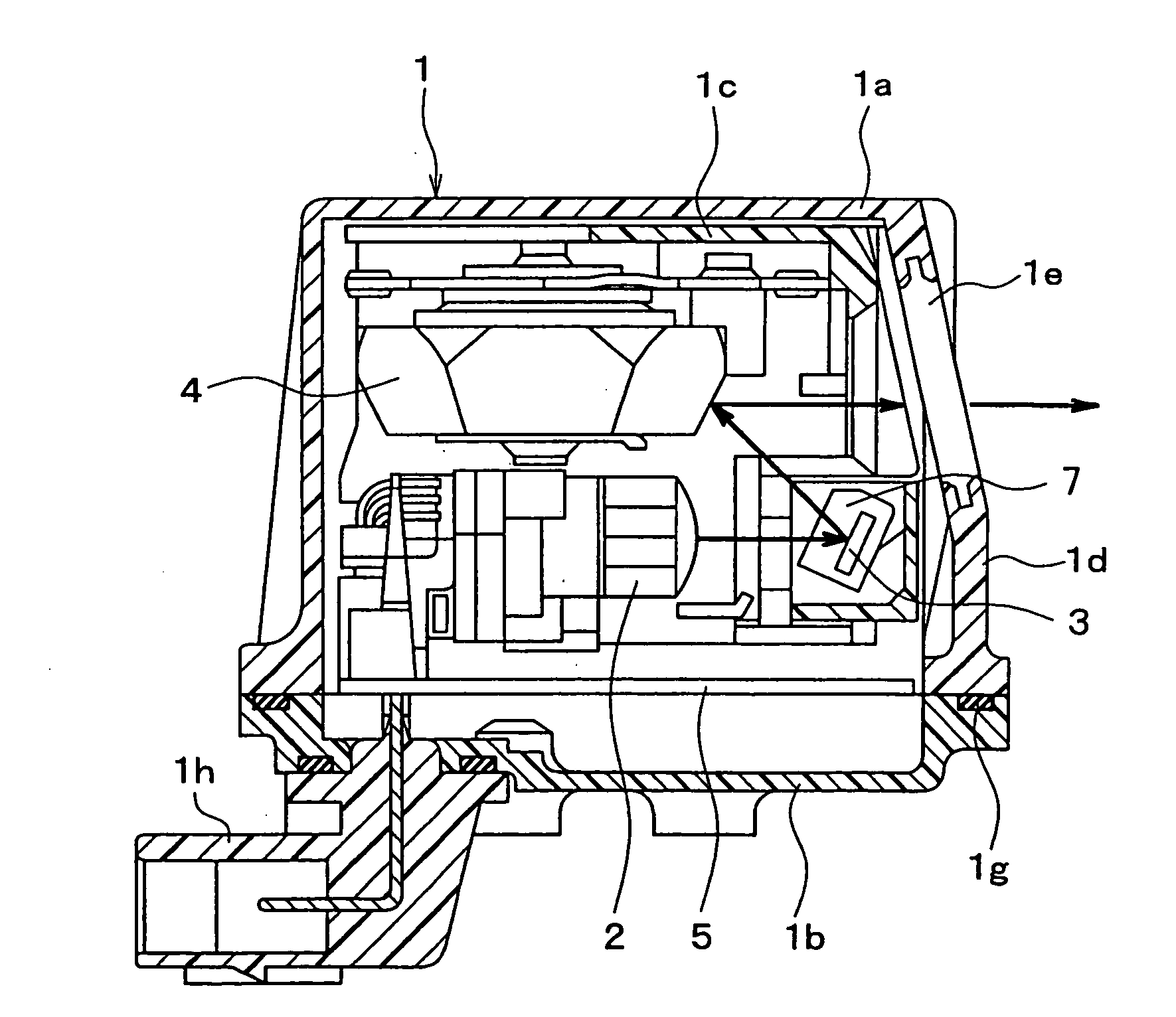
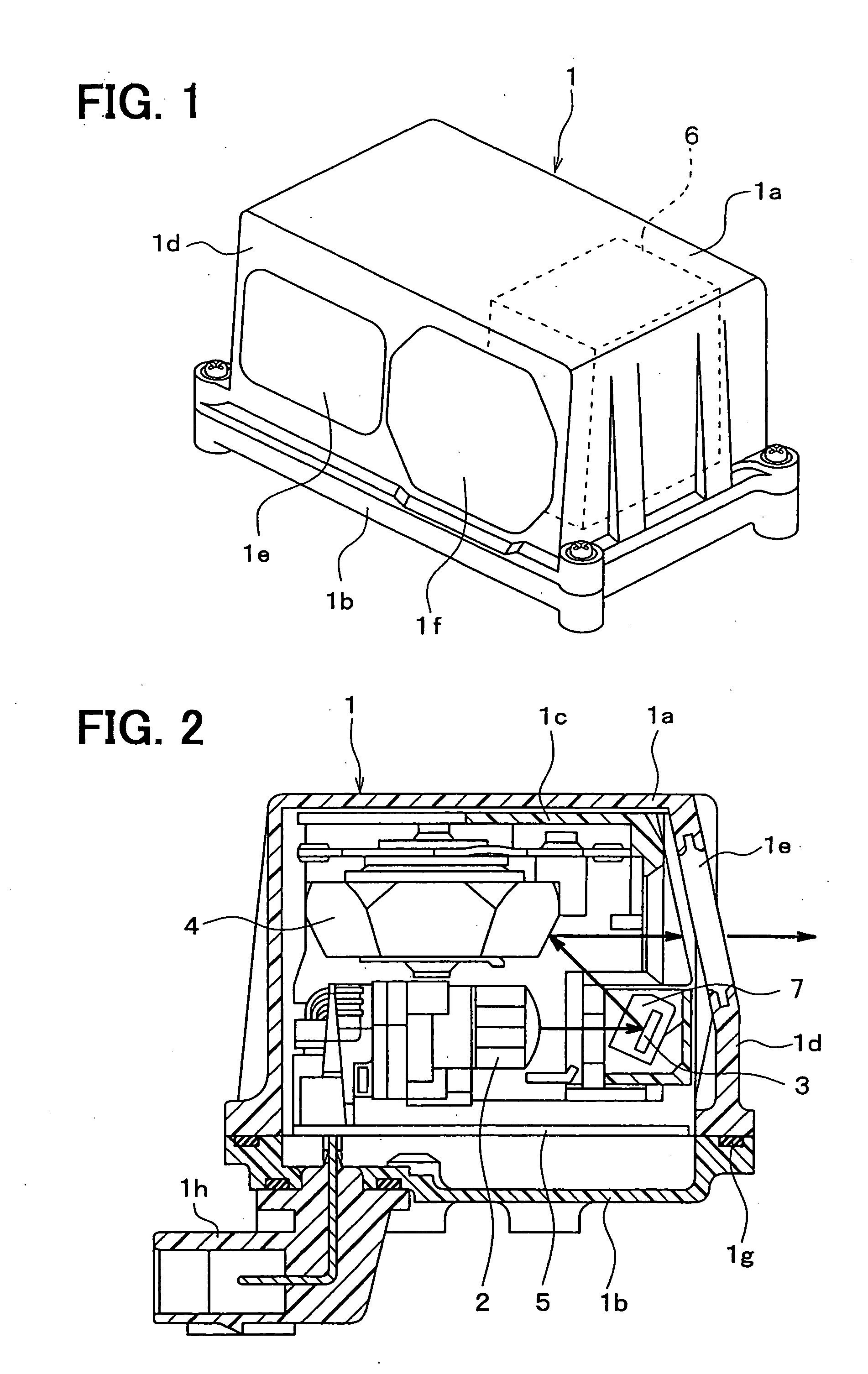
[0019] Referring first to FIGS. 1 to 3, an object detecting apparatus includes a case 1 shaped in a cuboid and various component parts accommodated in the case 1. The apparatus is mounted on a vehicle to be used as a laser radar. The apparatus is positioned to radiate a laser light in the forward direction of the vehicle (rightward direction in FIG. 2) to detect a distance to a forward object such as a preceding vehicle during an auto-cruise control condition.

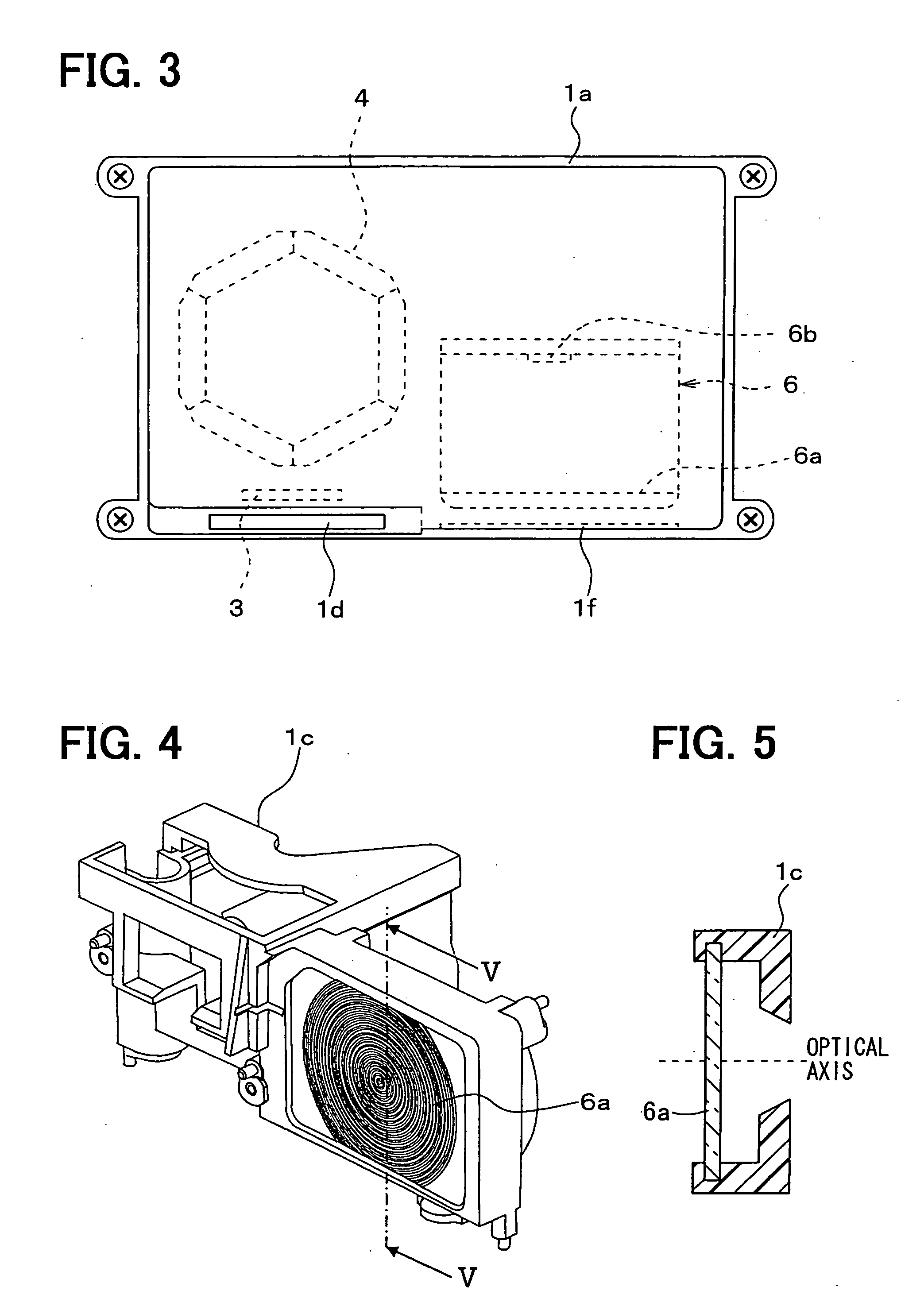
[0020] The apparatus includes a first outer case 1a, a second outer case 1b and an inner case 1c. The first case 1a is box-shaped and open at its one side (bottom side in FIG. 2). The first case 1a accommodates therein various component parts. The first case 1a has a resin part 1d made of black PPS resin and form a housing. The first case 1a has a light radiating window 1e and a light receiving window 1f arranged at the left and the right sections on the front-side resin part 1d. The windows 1e and 1f may be made of light tran...


PUM


Abstract

An object detecting apparatus comprises a light radiation unit and a light receiver unit disposed in an outer case. The light receiver unit includes a light collecting lens and a light receiving element. The light collecting lens is integrated with an inner case that is disposed in the outer case. The inner case is resin-molded with the light collecting lens by placing the light collecting lens in a pair of dies and injecting resin into the dies. Thus, the optical axis of the light collecting lens is fixed relative to the inner case, and hence it becomes in alignment with the optical axis of the light radiated by the radiation unit when the radiation unit is attached to the inner case.

Description

CROSS REFERENCE TO RELATED APPLICATION [0001] This application is based on and incorporates herein by reference Japanese Patent Application No. 2004-43182 filed on Feb. 19, 2004. FIELD OF THE INVENTION [0002] The present invention relates to an object detecting apparatus mounted on a vehicle, for instance, for detecting an object such as a preceding vehicle or a distance to such an object by using a light wave and to a manufacturing method for the same. BACKGROUND OF THE INVENTION [0003] A conventional object detecting apparatus mounted on a vehicle uses a laser light, for instance, to detect an object such as a preceding vehicle or a distance to such an object. This detecting apparatus intermittently drives a laser diode to radiate the laser light towards the forward side of the vehicle, and detects the light reflected from the forward obstacle by a photo sensor. The detecting apparatus measures the distance to the forward obstacle based on a time difference between a light radiati...

Claims


Application Information

Patent Timeline
IPC IPC(8): B60R21/00G01S7/48G01S7/481G01S7/497G01S17/08G01S17/931G06M7/00H01J40/14
CPCG01S7/4972G01S17/936G01S17/08G01S17/931
Inventor INOMATA, MAKOTO
Owner DENSO CORP
Why Eureka
Try Eureka