Integrated optical system for endoscopes and the like

Inactive Publication Date: 2006-08-31
INTEGRATED ENDOSCOPY
View PDF35 Cites 0 Cited by
  • Summary
  • Abstract
  • Description
  • Claims
  • Application Information

AI Technical Summary

Benefits of technology

[0013] Broadly, the foregoing advantages are achieved in a lens system which is characterized by an integrated design which has an external entrance pupil and in which the majority of the groups are displaced from the image planes and pupil planes. In this way most components share in the pupil transfer as well as in the image transfer. Moreover, the aberration correction is distributed in an advantageous way over all the groups, providing relief to the first group which conventionally is in need of most of the aberration correction. It has been found that this integration of the optical functions and aberration correction is very beneficial in that it greatly simplifies the optical system.
[0014] A plano-convex lens, or even a double convex lens when used according to the invention can be corrected for astigmatism since it is displaced from the stop location. In this way no optical surfaces of very short radii are needed to correct the astigmatism of the total optical system. Furthermore, the spherical aberration of a convex-plano lens used in the present invention is very near the minimum possible for a single element. Also the chromatic aberration is greatly reduced by the displacement of the elements from the image planes and pupil planes as a comparison with the classical arrangement will readily show. A factor two to four in the reduction of the chromatic aberration is thus achieved without the presence of a chromatic aberration reducing element, sometimes making further color correction unnecessary. Even a system incorporating several transfers is fully color corrected by the use of a single color correcting element. The distortion, which is usually very high in the objective, is corrected at more convenient and effective places. The result is a single integrated system which replaces the three conventional separate parts, i.e. the objective, the field lens, and a relay lens. This single integrated system may be augmented, as is well known in the art of optical design, with additional optics, like a close-up lens, a field expander, a field flattening lens, or with additional relay groups, without falling outside the scope of the invention.

Problems solved by technology

The system leads itself to mass production and is highly insensitive to tilt and decentration of its components.

Method used


Image

  • Integrated optical system for endoscopes and the like
  • Integrated optical system for endoscopes and the like
  • Integrated optical system for endoscopes and the like

Examples


Embodiment Construction

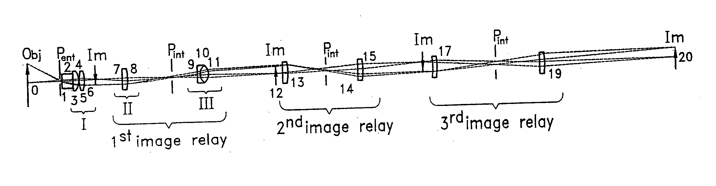
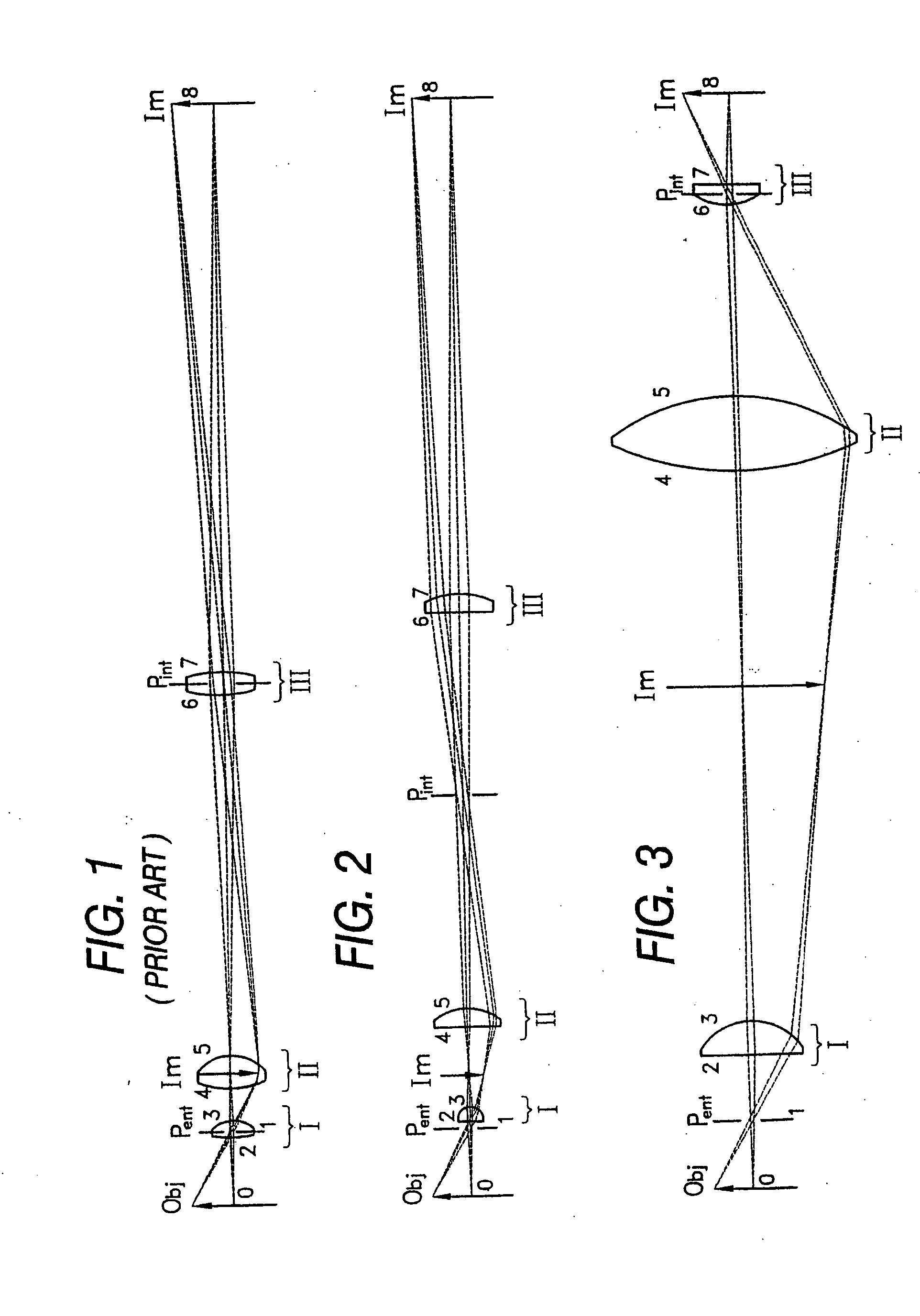
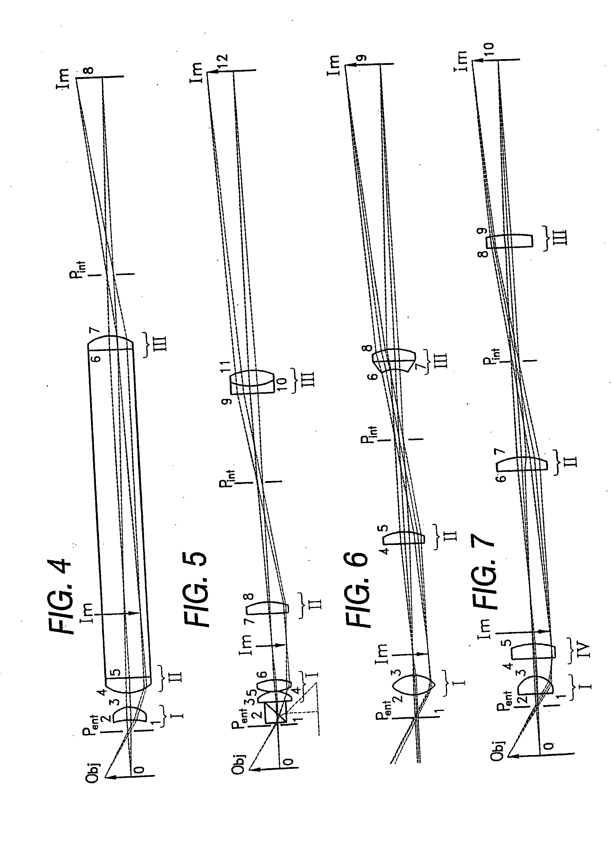
[0026] The illustrative embodiments to be described below are standardized to a length of about 100 millimeters of the basic optical system and mostly for a nominal magnification of unity. In this way the performance of the various examples can be conveniently compared. Embodiments with other magnifications, field of views, numerical apertures, and with additional relays are presented in order to show that the general concept of the invention is effective over a wide range of applications. The embodiments use conventional, non-GRIN (graded refractive index) lens elements, and thus each lens has a uniform refractive index. In FIGS. 1 through 11 the object and image planes are indicated by an ‘O’ and ‘Im’, respectively and the pupil planes by a ‘P’. The optical system features of object plane, pupil plane, lens surfaces and final image plane are numbered sequentially. Table I through XI present the constructional parameters of the preferred embodiments illustrated in corresponding FIG...


PUM


Abstract

Optical systems for endoscopes, borescopes, dental scopes, and the like which are characterized by having three groups of lenses of positive optical power and an external entrance pupil. Typically, all three groups of lenses are displaced from the pupil and focal planes. As a consequence, the displaced groups take part in the image transfer as well as in the pupil transfer. The optical power requirements can thus be shifted from one group to another, distributing as well as reducing the overall power requirement. Moreover, the aberration correction can also be shared between these groups. The first group, which conventionally has the highest optical power, and consequently a large amount of aberrations to be corrected, can in this way transfer some of the optical aberration correction to the other groups. The sharing of the optical functions and aberration correction results in a fully integrated optical system. The reduction in the total amount of optical power is so large that a line-of-sight deviating prism can be readily accommodated between the entrance pupil and the first lens group. The resulting simplicity of the optical system makes it suitable as a disposable item.

Description

PRIORITY APPLICATION [0001] This application is a continuation application of copending U.S. patent application Ser. No. 09 / 197,590, filed Nov. 23, 1998, now U.S. Pat. No. ______, which is a continuation application of U.S. patent application Ser. No. 08 / 687,910, filed Jul. 30, 1996, now U.S. Pat. No. 5,841,578, which is a continuation of U.S. patent application Ser. No. 08 / 351,481, filed Dec. 6, 1994, now U.S. Pat. No. 5,633,754, each of which is hereby incorporated herein by reference in their entirety.FIELD OF THE INVENTION [0002] The present invention relates generally to optical lens systems, and more particularly to lens systems suitable for endoscopes and the like. BACKGROUND OF THE INVENTION [0003] In endoscopy and related fields, such as borescopes and dental scopes, the complete optical system is thought of as consisting of four basic and separate optical functions. Those functions are, in sequence of the direction of the travelling light, as follows: [0004] 1. an objectiv...

Claims


Application Information

Patent Timeline
IPC IPC(8): G02B23/24G02B23/26
CPCG02B13/0095G02B23/2407G02B23/243G02B23/2446
Inventor HOOGLAND, JAN
Owner INTEGRATED ENDOSCOPY
Why Eureka
Try Eureka