Position sensing method and apparatus for synchronous motor generator system

a synchronous motor and rotor technology, applied in the direction of motor/generator/converter stopper, electronic commutator, dynamo-electric converter control, etc., can solve the problems of increasing system complexity, reducing system reliability, and needing unwanted extra wiring in the system, so as to facilitate accurate position detection, increase the position detection range of the position sensing apparatus, increase the effect of the position detection method

Active Publication Date: 2005-08-25
HONEYWELL INT INC
View PDF15 Cites 18 Cited by
  • Summary
  • Abstract
  • Description
  • Claims
  • Application Information

AI Technical Summary

Benefits of technology

[0010] In one aspect, the present invention is a method and an apparatus for deriving the rotor position of a brushless synchronous machine by monitoring the output of stator phase windings and varying an excitation frequency as mechanical rotation speed of the rotor increases to facilitate accurate position detection from the monitored signals. In one aspect, the present invention is a position sensing apparatus for deriving rotor position of a synchronous machine from signals output from the machine, the apparatus comprising: a bandpass filter that filters phase voltage signals output from main stator windings of the synchronous machine during AC excitation, thereby extracting a rotor position-indicating component from the phase voltage signals; a converter that converts the filtered phase voltages into balanced two-phase quadrature signals, the balanced two-phase quadrature signals indicating rotor position; and an excitation controller for controlling AC excitation frequency as a function of rotor speed, thereby increasing the position detection range of the position sensing apparatus.
[0011] In another aspect, the present invention is a method for determining the rotor position of a synchronous machine from signals output from the machine, the method comprising: bandpass filtering of phase voltage signals output from main stator windings of the synchronous machine during AC excitation, thereby extracting a rotor position-indicating component from the phase voltage signals; converting the filtered phase voltages into balanced two-phase quadrature signals, the balanced two-phase quadrature signals indicating rotor position; and controlling AC excitation frequency as a function of rotor speed, thereby increasing a position detection range of the position sensing method.

Problems solved by technology

This technique, however, increases system complexity and decreases system reliability.
The location of the rotating machine could be far from the controller, creating the need for unwanted extra wiring in the system.
Some of these systems have synchronous generators that can be used as a motor generator but they do not have discrete sensors.
However, although the above-described system operates as in a sensorless mode, it requires that the position sensing take place only on the non-commutated stator windings.
Accordingly, the position sensor emulation must shift from phase to phase as respective phases are commutated, which complicates the sensor emulation.
Further, prior art sensorless systems fail to provide initial position sensing at standstill or low speed ranges that is necessary at start-up under high load torque of the motor generator.

Method used


Image

  • Position sensing method and apparatus for synchronous motor generator system
  • Position sensing method and apparatus for synchronous motor generator system
  • Position sensing method and apparatus for synchronous motor generator system

Examples


Embodiment Construction

[0019] Embodiments of the present invention are more specifically set forth in the following description, with reference to the appended drawings. In the following description and accompanying drawings like elements are denoted with similar reference numbers. Further, well-known elements and related explanations are omitted so as not to obscure the inventive concepts presented herein.

[0020] U.S. patent application Ser. No. 10 / 244,496 (“the '496 application”), filed Sep. 16, 2002 and titled “Position Sensor Emulator for a Synchronous Motor / Generator,” which discloses embodiments for deriving rotor position information from phase voltage signals output by main generator stator windings (stator phase windings) of a synchronous motor generator, is incorporated herein by reference.

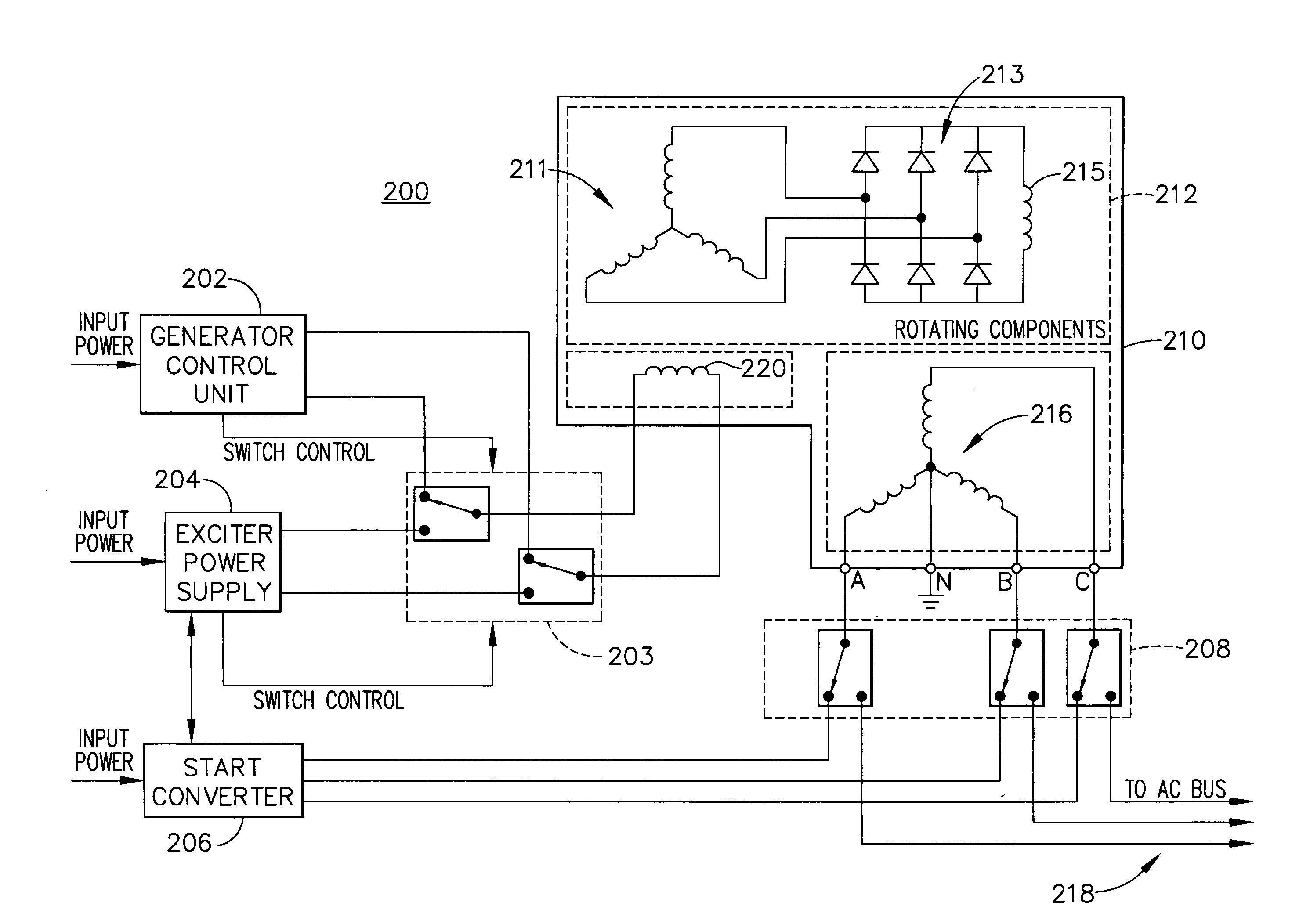
[0021]FIG. 2 illustrates a synchronous motor generator system 200 to which principles of the present invention may be applied to derive rotor position from signals output from stator phase windings. The synch...


PUM


Abstract

A position sensing apparatus (300) derives rotor position of a synchronous machine (200) from signals output from the machine (200). In one embodiment, the position sensing apparatus (300) comprises: a bandpass filter (322) that filters phase voltage signals output from main stator windings (216) of the synchronous machine (200) during AC excitation, thereby extracting a rotor position-indicating component from the phase voltage signals; a converter (324) that converts the filtered phase voltages into balanced two-phase quadrature signals, the balanced two-phase quadrature signals indicating positioning of the rotor (212); and an excitation controller (204) for controlling AC excitation frequency as a function of rotor speed.

Description

FIELD OF THE INVENTION [0001] The present invention relates to synchronous machines, and more particularly to a method and apparatus for detecting rotor position in a synchronous motor generator system. BACKGROUND OF THE INVENTION [0002] A conventional motor generator system, as utilized for example in the aerospace industry, includes a brushless synchronous machine that generates multi-phase AC power from a rotating shaft, e.g., coupled to a gas turbine engine, and DC excitation. In addition to operating in a generator mode, the brushless synchronous machine operates as a starter (motor) to start the aircraft engine. Following a successful engine start the system initiates the generator mode. [0003] Conventionally, motor controllers for applications requiring a controlled torque use discrete sensors to determine rotor position in a rotating machine. This technique, however, increases system complexity and decreases system reliability. The electric machine must have a sensor built i...

Claims


Application Information

Patent Timeline
Patent Type & Authority Applications(United States)
IPC IPC(8): H02P6/18H02P9/00
CPCH02P6/185H02P2101/30H02P9/007
Inventor ANGHEL, CRISTIAN E.DIVITO, ROCCOMORCOV, NICOLAE A.
Owner HONEYWELL INT INC
Why Eureka
Try Eureka