Method and system for measuring partial discharge

a partial discharge and measurement method technology, applied in the field of partial discharge measurement methods and systems, can solve the problem of difficult detection of accurate partial discharge signal patterns, and achieve the effect of accurately measuring phase shifts and accurate compensating phase shifts

Inactive Publication Date: 2005-08-25
HITACHI LTD +1
View PDF1 Cites 11 Cited by
  • Summary
  • Abstract
  • Description
  • Claims
  • Application Information

AI Technical Summary

Benefits of technology

[0007] To achieve the above objective, when measuring partial discharge by using a measuring instrument which displays input information on its screen, the present invention detects voltages of the conductor encased in the container; converts the waveform of the operating voltage (alternating voltage), among detected voltages, applied to the conductor by using a signal converter circuit; inputs the converted operating voltage into the measuring instrument; detects the phase difference between the measuring instrument's power-supply voltage and the operating voltage based on the inputted operating voltage; compensates the phase of the time axis displayed on the measuring instrument's screen according to the detected phase difference; and inputs the detected voltage into the compensated measuring instrument as it is, thereby displaying partial discharge information on the measuring instrument's screen. In this case, if there is a voltage phase shift associated with input impedance of the signal converter circuit, it is possible to further accurately compensate phase shifts by considering the voltage phase shift and compensating the phase of the time axis displayed on the screen of the measuring instrument.
[0008] According to the present invention, partial discharge can be accurately measured.

Problems solved by technology

Accordingly, if the signal which has had its phase changed is processed in the signal processing section, even if a partial discharge signal is detected by using an alternating voltage (operating voltage) as a trigger, it is difficult to detect an accurate pattern of the partial discharge signal.

Method used


Image

  • Method and system for measuring partial discharge
  • Method and system for measuring partial discharge
  • Method and system for measuring partial discharge

Examples


first embodiment

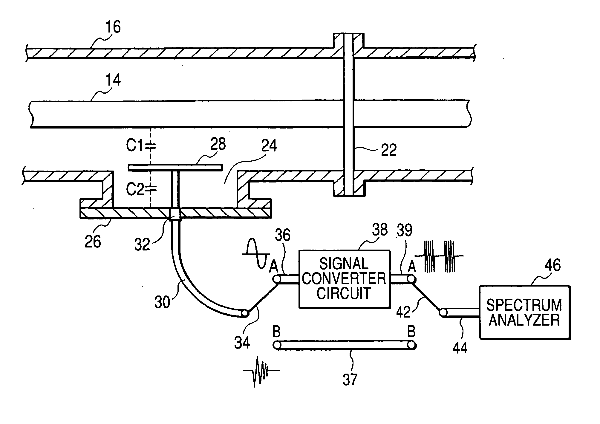
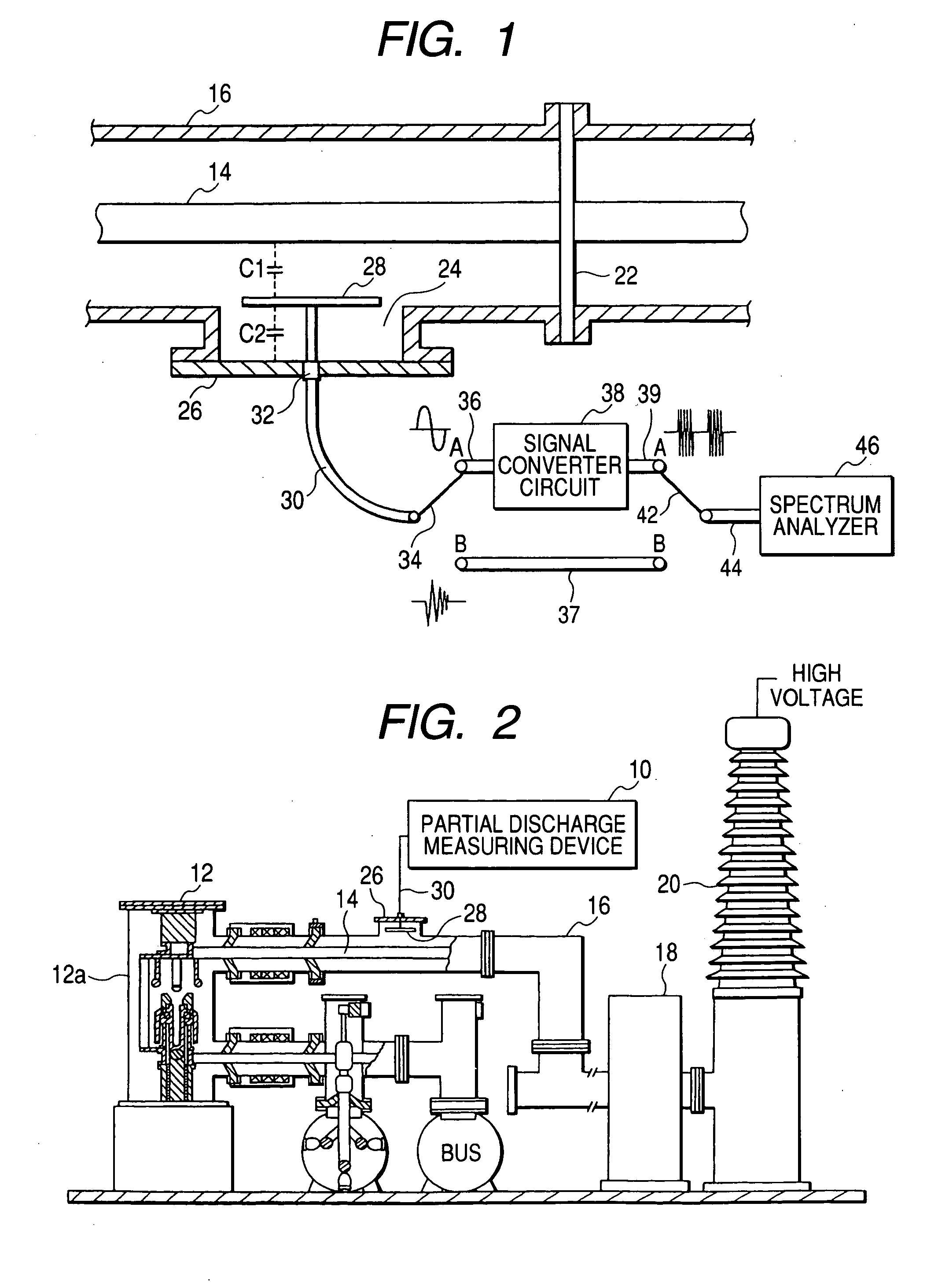
[0016] Hereafter, an embodiment of the present invention will be explained with reference to the drawings. FIG. 1 is a block diagram of a partial discharge measuring device according to the present invention, and FIG. 2 is a side cross-sectional view of the major portion when the partial discharge measuring device is installed in an gas insulated device.

[0017] In FIGS. 1 and 2, the partial discharge measuring device 10 is installed in the vicinity of the metal container 16, which encases a high-voltage conductor 14 and an insulation material, so as to measure one phase of the high-voltage conductor 14 which is a gas insulated bus connected to a gas circuit breaker 12. One end of the high-voltage conductor 14 is connected to an electrode of the gas circuit breaker 12, and the other end is exposed to the atmosphere via an arrester 18 and a bushing 20. For example, 60,000 to 500,000 volt alternating voltage is applied to the high-voltage conductor 14 as an operating voltage. The high-v...

second embodiment

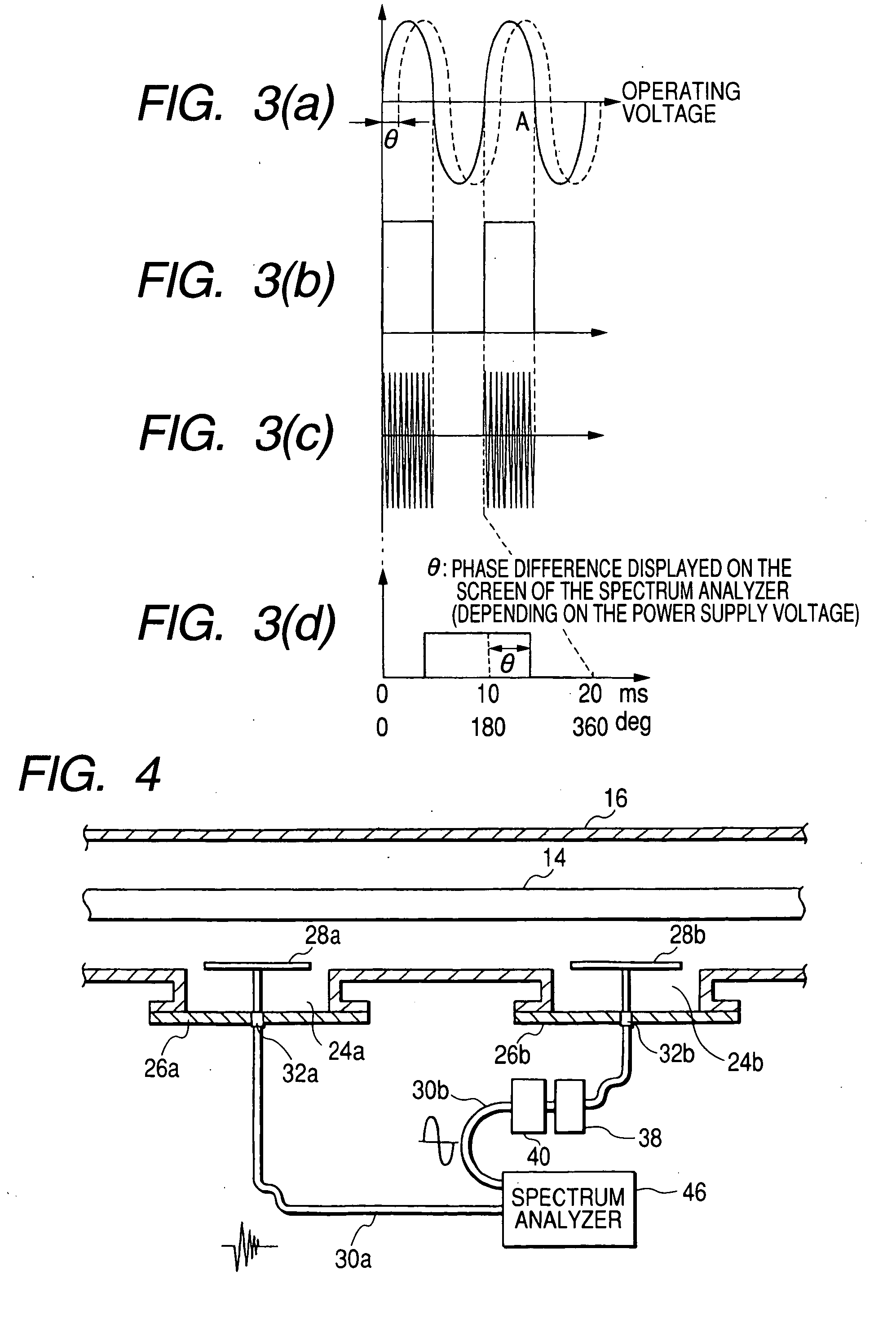
[0027] Next, the present invention will be explained with reference to FIG. 4. In this embodiment, antennas 28a and 28b which have the same function as an antenna 28 are encased in hand holes 24a and 24b, respectively, and each antenna 28a and 28b is connected to a spectrum analyzer 46 via a coaxial cable 30a or 30b, and a signal converter circuit 38 and a delay circuit 40 are inserted in the middle of the coaxial cable 30b. The other configuration is the same as that shown in FIG. 1. To equalize the propagation time of each signal that is transmitted through coaxial cables 30a and 30b, the lengths of the coaxial cables 30a and 30b are the same.

[0028] The antenna 28a functions as a voltage sensor to detect partial discharge, and the antenna 28b functions as a voltage sensor to detect an operating voltage applied to the high-voltage conductor 14. The operating voltage signal detected by the antenna 28b is formed into a waveform by a signal converter circuit 38, and delayed by the del...

third embodiment

[0030] Next, the present invention will be explained with reference to FIG. 5. In this embodiment, instead of using an antenna 28b as a voltage sensor, an electromagnetic wave sensor 50 which is disposed around the insulating support medium 22 and detects an operating voltage applied to the high-voltage conductor 14 is used, and instead of using a spectrum analyzer 46, an oscilloscope 52 is used. The other configuration is the same as that shown in FIG. 4. This embodiment uses an oscilloscope 52 as a measuring instrument which displays input information on its screen. Accordingly, a coaxial cable 30a is connected to a measurement signal input terminal of the oscilloscope 52, and a coaxial cable 30b is connected to a trigger signal input terminal of the oscilloscope 52.

[0031] In this embodiment, the operating voltage signal detected by an electromagnetic wave sensor 50 functions as a trigger, and partial discharge signals detected by an antenna 28a are sequentially displayed on the s...


PUM


Abstract

Prior to the measurement of partial discharge, a voltage detected by the antenna is inputted into a spectrum analyzer, a phase difference between an operating voltage and a power supply of the spectrum analyzer is obtained by phase domain analysis using the spectrum analyzer. Based on the phase difference and the voltage phase shift associated with input impedance of the signal converter circuit, the time axis displayed on the screen of the spectrum analyzer is compensated. After the compensation has been carried out, the voltage detected by the antenna is inputted into the spectrum analyzer, the partial discharge pattern which synchronizes with the operating voltage is measured by phase domain analysis using the spectrum analyzer.

Description

CLAIM OF PRIORITY [0001] The present application claims priority from Japanese application serial no. 2004-44926, filed on Feb. 20, 2004, the content of which is hereby incorporated by reference into this application. FIELD OF THE INVENTION [0002] The present invention relates to a partial discharge measurement method and a system, and specifically to a partial discharge measurement method and a system suitable for measuring partial discharge which results from an insulation defect in a container filled with insulating gas used as an insulation material. BACKGROUND OF THE INVENTION [0003] The gas insulated device, such as a gas circuit breaker, gas insulated switchgear and gas insulated bus, which is used in a transmission and delivery system is structured such that a high-voltage conductor is encased in a sealed metal container filled with an insulating gas and is supported by an insulating support medium. If a defect, such as a metal particle, is present in the sealed metal contai...

Claims


Application Information

Patent Timeline
Patent Type & Authority Applications(United States)
IPC IPC(8): G01R31/12
CPCG01R31/1272G01R31/1254G01R31/12
Inventor MORIYAMA, TOMOHIROKATO, TATSUROROKUNOHE, TOSHIAKIENDO, FUMIHIROSHINOHARA, RYOICHI
Owner HITACHI LTD
Why Eureka
Try Eureka