Liquid crystal display apparatus

Active Publication Date: 2005-08-25
PANASONIC LIQUID CRYSTAL DISPLAY CO LTD +1
View PDF12 Cites 545 Cited by
  • Summary
  • Abstract
  • Description
  • Claims
  • Application Information

AI Technical Summary

Benefits of technology

[0022] Correction (90p4) of the video signal is carried out on the basis of an illumination luminance distribution between areas (90p3), whereby a picture of high contrast ratio and less irregularities can be obtained and consumptive power of the lighting unit can be reduced.
[0023] In determination (90p2) of rays of the illumination light of individual areas which are emitted from the lighting unit, the illumination light is determined by correcting (90p4) the video signal such that an area of good characteristic ((c) in FIG. 31) of the light modulation device can be used, whereby a picture of high contrast ratio and less irregularities can be obtained, consumptive power of the lighting unit can

Problems solved by technology

In the non-luminous type display apparatus such as liquid crystal display apparatus described in the background arts, a sufficient contrast ratio, in other words, a wide display luminance range cannot be obtained.
The aforementioned background arts disclose techniques of controlling the luminance of backlight for the sake of various purposes but any of them have difficulties with maintaining picture quality.
For example, in the case of the method of controlling the luminance of the overall screen by adjusting the luminance of backlight, when a locally bright area exists in a picture and the luminance of the backlight is raised, the luminance of a dark area coexistent in the picture rises an

Method used


Image

  • Liquid crystal display apparatus
  • Liquid crystal display apparatus
  • Liquid crystal display apparatus

Examples


embodiment 1

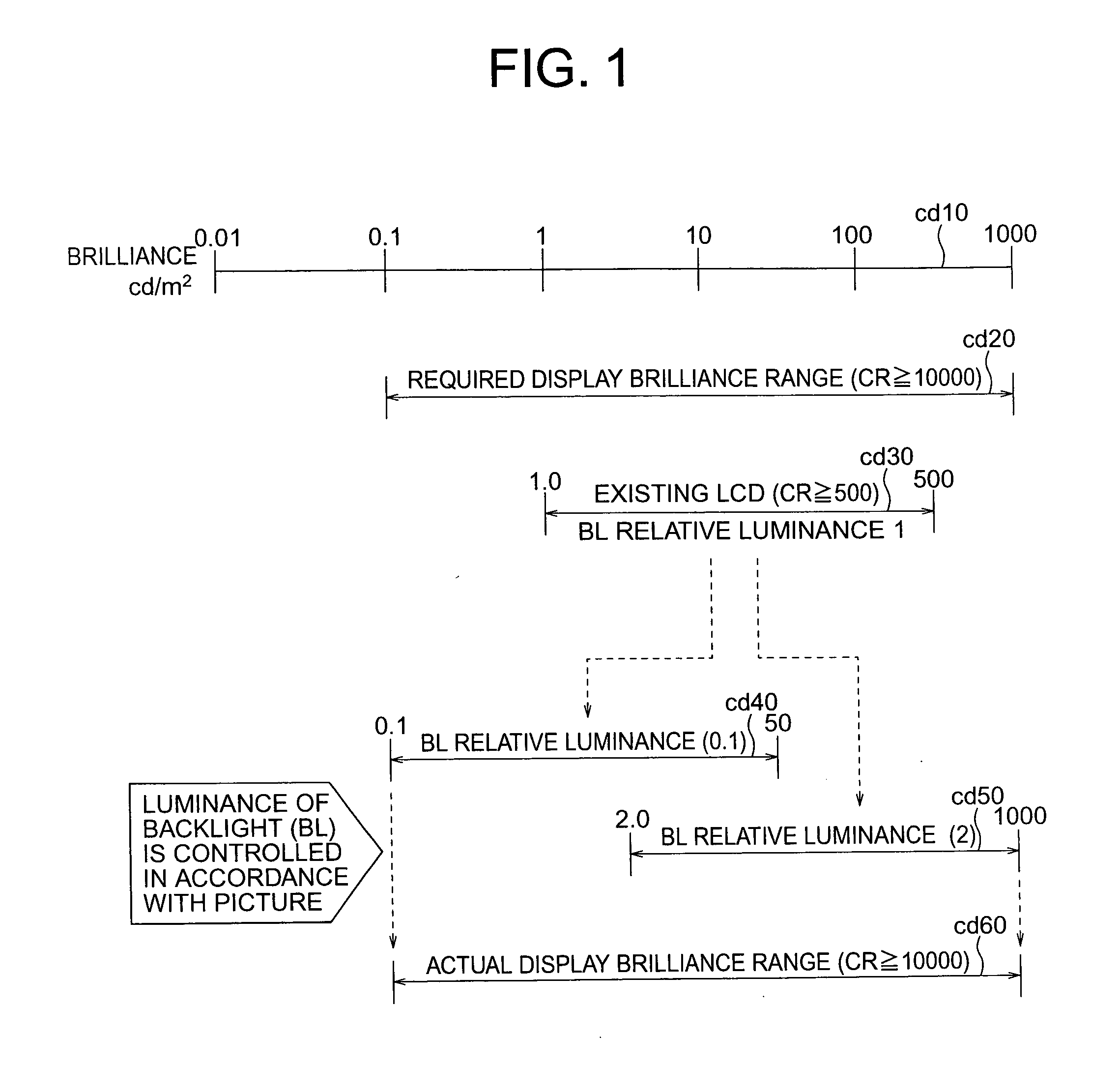
[0080]FIG. 1 to FIGS. 11A and 11B are illustrative of embodiment 1 of the invention and firstly, raising the contrast ratio by widening the display luminance range will be described with reference to FIG. 1.

[0081] It is assumed that in FIG. 1, an existing liquid crystal display apparatus has a backlight (BL) which exhibits a relative luminance defined as 1. In case an ideal display luminance range (cd10) is 0.01 cd / m2 to 1000 cd / m2, a display luminance range (cd20) from 0.1 cd / m2 to 1000 cd / m2 and a contrast ratio (CR)≧10000 are required for the liquid crystal display apparatus.

[0082] But, the liquid crystal display apparatus exhibits at present a display luminance range (cd30) which is 1.0 cd / m2 to 500 cd / m2 and a small contrast ratio (CR) of 500. This is accounted for by the fact that in the liquid crystal display apparatus explained in the background arts, the backlight is lit constantly at constant luminance regardless of a video signal and as a result, part of light of the ba...

embodiment 2

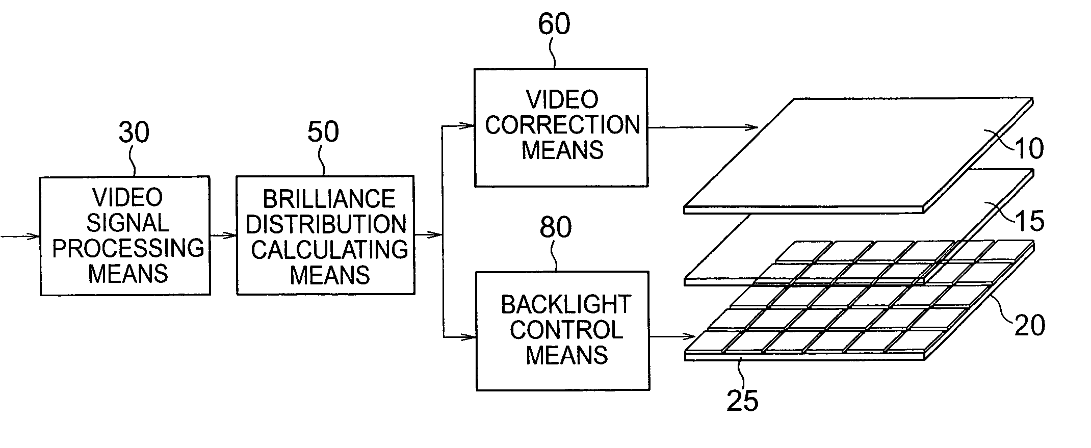
[0110] Embodiment 2 of this invention will be described hereunder with reference to FIG. 12 through FIGS. 17A to 17D. In the present embodiment, the overall schematic construction shown in FIG. 3 according to this invention will be detailed and like parts will be designated by like reference numerals.

[0111] In FIG. 12, an LCD panel is driven by signal lines s90 of data driver 11 and signal lines s100 of gate driver 12. A data signal s70 to the data driver 11 is fed from a video correction means 60. Further, a timing signal s60 to the gate driver 12 is also fed from the video correction means 60.

[0112] An LED panel 20 functioning as a backlight is driven by signal lines s140 of column driver 21 and signal lines s150 of row driver 22. A column driver signal s115 and a PWM signal s120 are supplied to the column driver 21 from a backlight control means 80. A timing signal s110 to the row driver 22 is also fed from the backlight control means 80. A sensor is arranged at a predetermined...

embodiment 3

[0123] An embodiment of the lighting unit (backlight) will be described with reference to FIG. 18 through FIG. 29. A partitive area type backlight using light emitting diodes LED's is constructed as shown in FIG. 18 to function as a light emitting device for emitting illumination light. The LED panel 20 is divided into predetermined areas 25 and a plurality of (here, four) LED's are arranged in each area 25. The LED panel 20 is disposed immediately beneath the LCD panel 10 and a luminance distribution for individual areas 25 can be uniformed through the medium of a light diffusing sheet 15.

[0124] A basic model of matrix divie mode for the LED panel 20 is depicted in FIG. 19. As shown, a switching element M is disposed at an intersection of data line (DATAline) and scan line (SCANline) to switch on / off a switch SW in accordance with a potential difference between the data line (DATAline) and the scan line (SCANline). An electrical potential develops across two common electrode lines...


PUM


Abstract

The video display apparatus has a light modulation device for forming a picture in accordance with a video signal and a lighting unit for irradiating, on the light modulation device, illumination light necessary to cause it to display the picture. In the apparatus, the lighting unit irradiates the illumination light in sequence of individual plural illumination light source partitive areas, a luminance distribution calculating unit calculates luminance distributions of video signals corresponding to the plural partitive areas to determine illumination light luminance levels of the individual partitive areas, an illumination controller controls rays of the illumination light of individual areas of the lighting unit on the basis of determination by the luminance distribution calculating unit, and a video corrector corrects the video signal inputted to the light modulation device on the basis of the determination by the luminance distribution calculating unit.

Description

BACKGROUND OF THE INVENTION [0001] The present invention relates to a video display apparatus for displaying a picture by modulating illumination light in accordance with a video signal and more particularly to, a lighting unit for controlling the luminance of illumination light in accordance with video signals, a video display apparatus provided with the lighting unit and a video display method using the same. [0002] The display apparatus can be classified principally into a luminous display apparatus such as CRT (cathode ray tube) or plasma display panel and a non-luminous display apparatus such as liquid crystal display (also called a liquid crystal display apparatus or liquid crystal display panel) or electro-chromic display. [0003] Available as the non-luminous display apparatus are an apparatus of the type using a reflection type light modulation device adapted to adjust the quantity of reflection light in accordance with a video signal and an apparatus of the type using a tra...

Claims


Application Information

Patent Timeline
IPC IPC(8): G02F1/133G02F1/13357G02F1/1343G09G3/20G09G3/32G09G3/34G09G3/36
CPCG09G3/3208G09G2360/16G09G3/3426G09G3/346G09G3/3648G09G2300/023G09G2300/0434G09G2300/06G09G2310/08G09G2320/0233G09G2320/0238G09G2320/0247G09G2320/028G09G2320/0285G09G2320/029G09G2320/062G09G2320/064G09G2320/0646G09G2320/0653G09G2320/066G09G2320/103G09G2330/021G09G2360/144G09G2360/145G09G3/3225
Inventor KONNO, AKITOYOADACHI, MASAYAKAJITA, DAISUKEYAMAMOTO, TSUNENORIKONDO, KATSUMIINUZUKA, TATSUKIHIYAMA, IKUOUTSUMI, YUKA
Owner PANASONIC LIQUID CRYSTAL DISPLAY CO LTD
Why Eureka
Try Eureka