Serial line circuit

a serial line and circuit technology, applied in the field of serial communication, can solve the problems of discontinuing using such circuits, posing a number, and affecting the operation of the circuit,

Active Publication Date: 2005-08-25
ARUBA WIRELESS NETWORKS INC +1
View PDF4 Cites 12 Cited by
  • Summary
  • Abstract
  • Description
  • Claims
  • Application Information

AI Technical Summary

Problems solved by technology

This architecture poses a number of disadvantages, especially for electronic devices having multiple serial ports.
For instance, one disadvantage is that the total costs incurred in supporting multiple serial ports, such as a 24-serial port terminal server for example, is substantial.
These costs normally prompt manufacturers to discontinue using such circuits and provide consumers with inferior electronic devices, or such costs are passed on to consumers.
Another disadvantage is that these opto-isolators occupy a substantial amount of real estate when mounted on a circuit board.
Yet another disadvantage is that these opto-isolators require power at the electrically isolated side, which is expensive to supply.

Method used


Image

  • Serial line circuit
  • Serial line circuit
  • Serial line circuit

Examples


Embodiment Construction

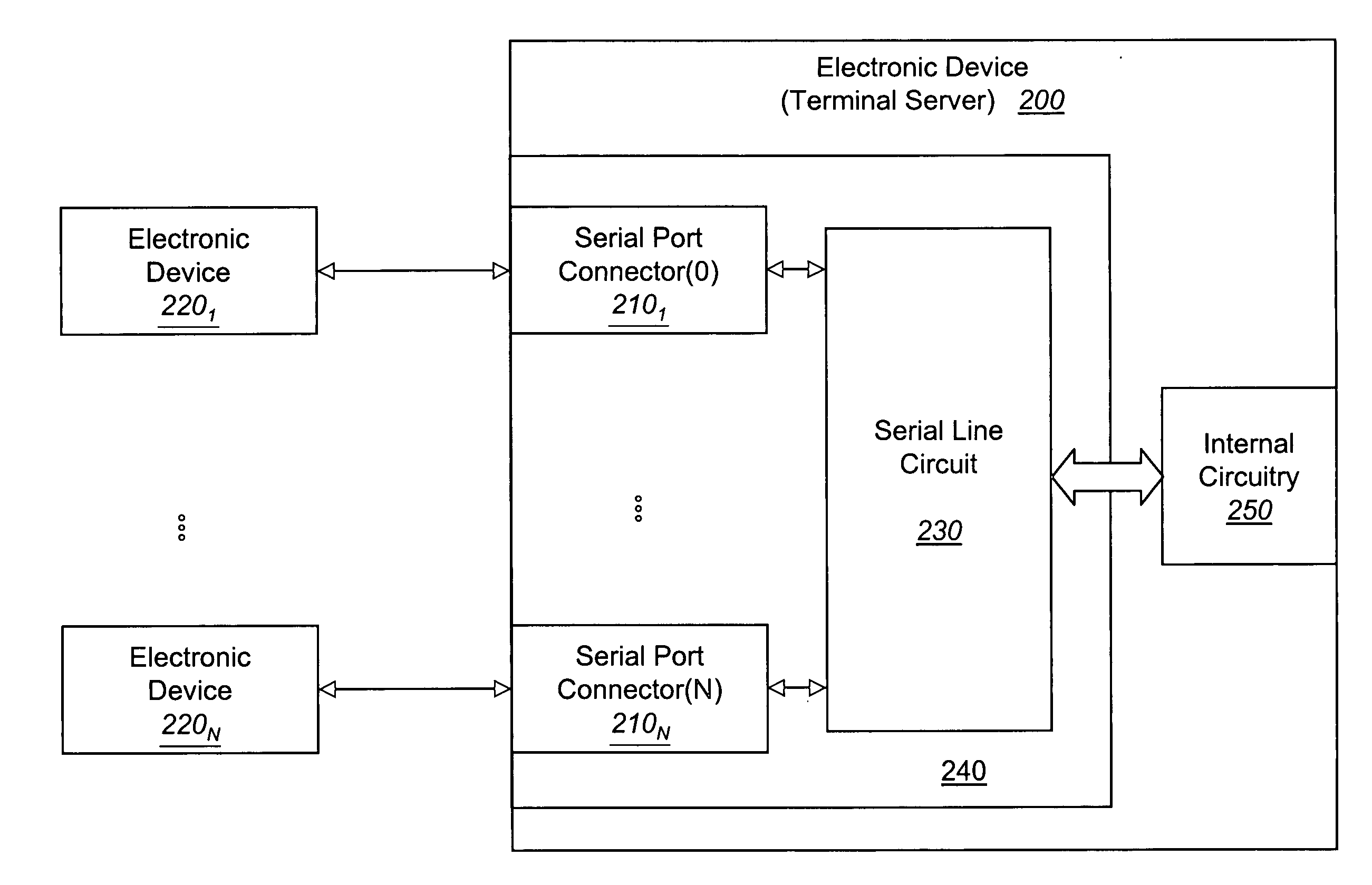
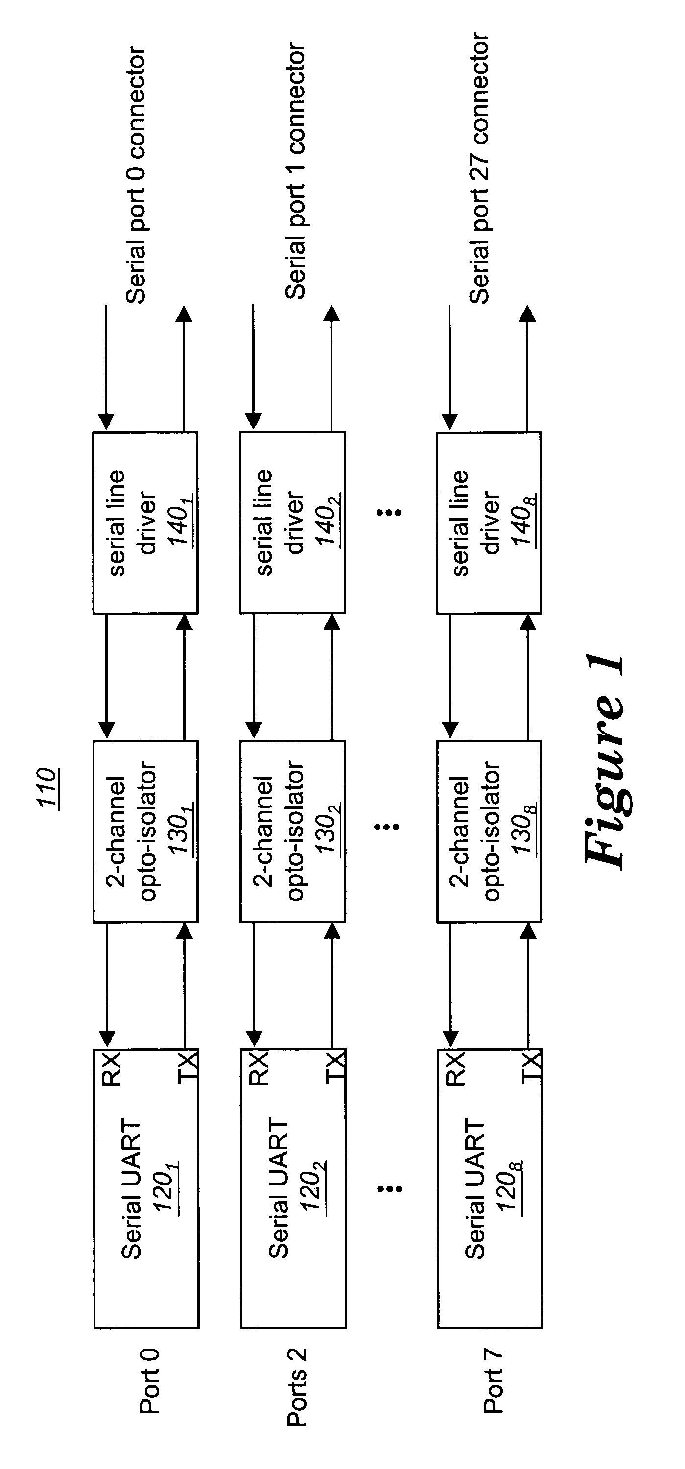
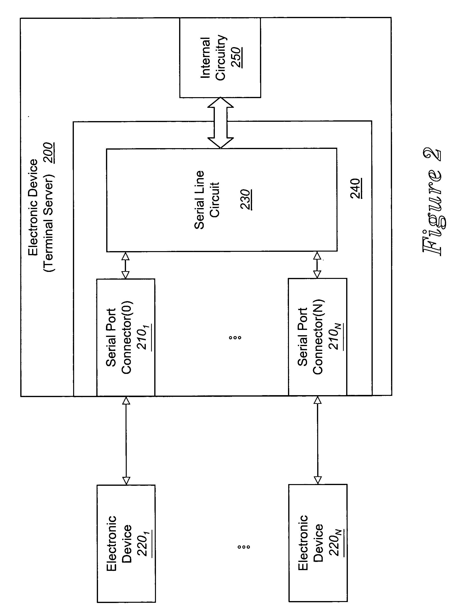
[0017] Herein, certain embodiments of the invention relate to a serial line circuit that comprises a serial information (SI) bus and at most two isolators interposed between a pair of programmable devices. In the TRANSMIT direction, a first programmable device is configured to multiplex serial data received from a plurality of serial UARTs and to route such data to the second programmable device over the SI bus and through a first isolator. In the RECEIVE direction, the second programmable device is configured to sample data from a plurality of serial interconnects and to route the sampled data to the first programmable device. The sampled data is routed over the SI bus and through a second isolator. The data transmission over the SI bus is in accordance with a proprietary serial transmission protocol described below.

[0018] Certain details are set forth below in order to provide a thorough understanding of various embodiments of the invention, albeit the invention may be practiced ...


PUM


Abstract

In one embodiment, the invention relates to a serial line circuit that comprises a serial information (SI) bus and at most two isolators interposed between a pair of programmable devices. In the TRANSMIT direction, a first programmable device is configured to multiplex serial data received from a plurality of serial UARTs and to route such data to the second programmable device over the SI bus and through a first isolator. In the RECEIVE direction, the second programmable device is configured to sample data from a plurality of serial interconnects and to route the sampled data to the first programmable device. The sampled data is routed over the SI bus and through a second isolator. The data transmission over the SI bus is in accordance with a proprietary serial transmission protocol described below.

Description

FIELD [0001] Embodiments of the invention relate to the field of serial communications, in particular, to a serial line circuit. GENERAL BACKGROUND [0002] For decades, servers and other types of electronic devices have been implemented with input / output (I / O) devices. One type of I / O device is a serial port, which is normally a 9-pin or 25-pin connector positioned along a physically accessible portion of the electronic device. Since data is normally processed in parallel within an electronic device, the serial port is adapted to convert data from a parallel format into a serial format. A serial universal asynchronous receiver transmitter (hereinafter referred to as a “UART”) normally performs this format conversion. [0003] As shown in FIG. 1, a conventional multi-port serial line circuit 110 implemented within an electronic device is shown. The conventional serial line circuit 110 features a plurality of serial UARTs 1201-1208 as well as corresponding dual channel opto-isolators 130...

Claims


Application Information

Patent Timeline
Patent Type & Authority Applications(United States)
IPC IPC(8): H04L12/50H04L25/02H04L29/06
CPCH04L29/06H04L25/0266H04L12/40039H04L9/40
Inventor ADAM, JOEL F.MARTINSON, JERRY
Owner ARUBA WIRELESS NETWORKS INC
Why Eureka
Try Eureka