Bass boost circuit and bass boost processing program

Inactive Publication Date: 2005-08-25
SANYO ELECTRIC CO LTD
View PDF4 Cites 18 Cited by
  • Summary
  • Abstract
  • Description
  • Claims
  • Application Information

AI Technical Summary

Benefits of technology

[0011] In addition, it is an object of the present invention to provide a bass boost circuit and a bass boost processing program in which the second harmonic is prevented from being generated for both reference wave and its harmonic so that

Problems solved by technology

The bass reproducing ability is limited by capacity of a speaker mainly.
Therefore, a sufficient bass reproducing ability cannot be provided in a small speaker used in a television and the like.
However, even if the bass can be recognized, there is not provided natural sound in this conventional technique because of the following reasons.
Therefore, although the harmonic is g

Method used


Image

  • Bass boost circuit and bass boost processing program
  • Bass boost circuit and bass boost processing program
  • Bass boost circuit and bass boost processing program

Examples


Example

[A] Description of Embodiment 1

[1] Description of a Bass Pseudo Reproducing Device

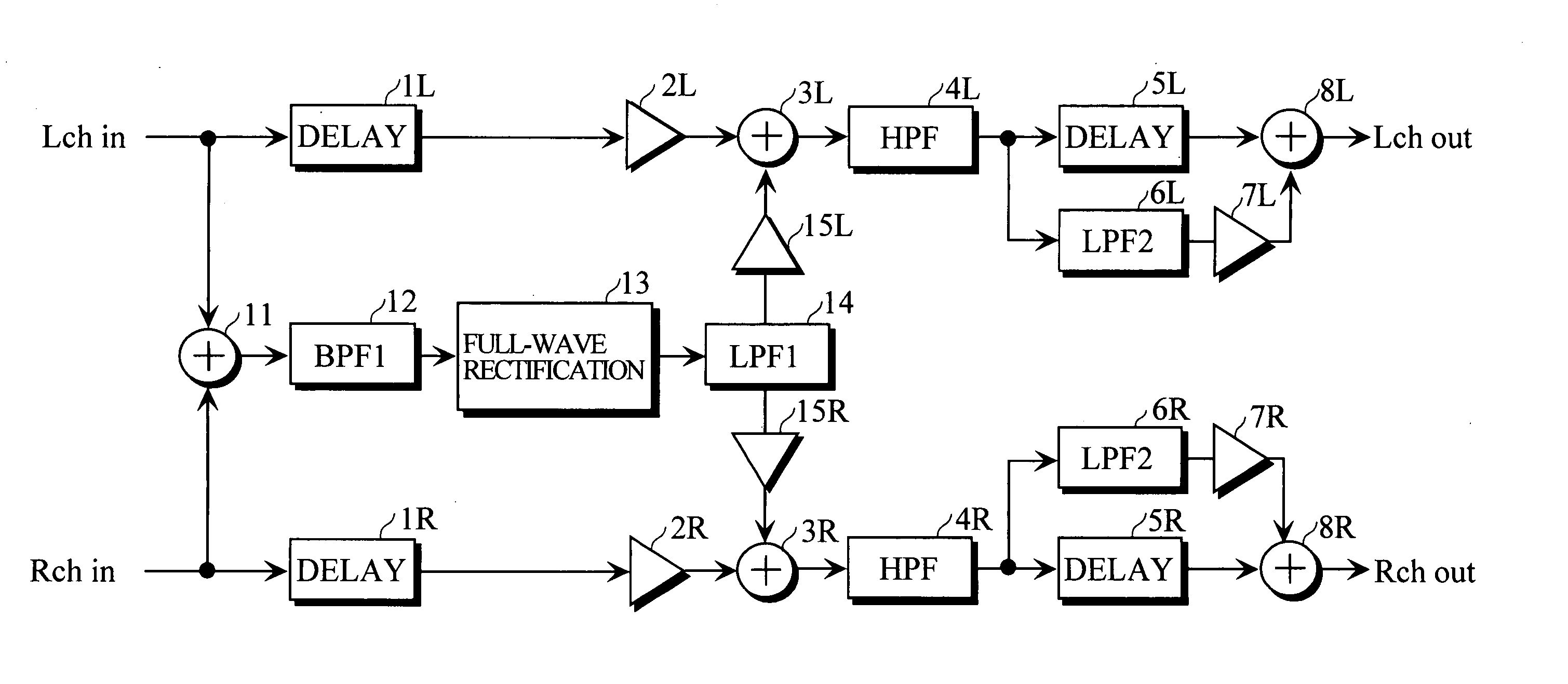
[0024]FIG. 1 shows a constitution of a bass boost circuit according to an embodiment 1.

[0025] Audio signals comprising an L channel signal (Lch in) and a R channel signal (Rch in) are inputted to the bass boost circuit. The L channel signal is transmitted to an adder 3L through a delay circuit 1L and an amplifier 2L. In addition, the L channel signal is transmitted to an adder 11 also. The R channel signal is transmitted to an adder 3R through a delay circuit 1R and an amplifier 2R. In addition, the R channel signal is also transmitted to the adder 11.

[0026] The L channel signal and the R channel signal are added in the adder 11. An output of the adder 11 is transmitted to a full-wave rectification circuit 13 through a band-pass filter (BPF1) 12 which transmits only a signal of a predetermined frequency. Characteristics and a function of the band-pass filter (BPF1) 12 will be described below. The...

Example

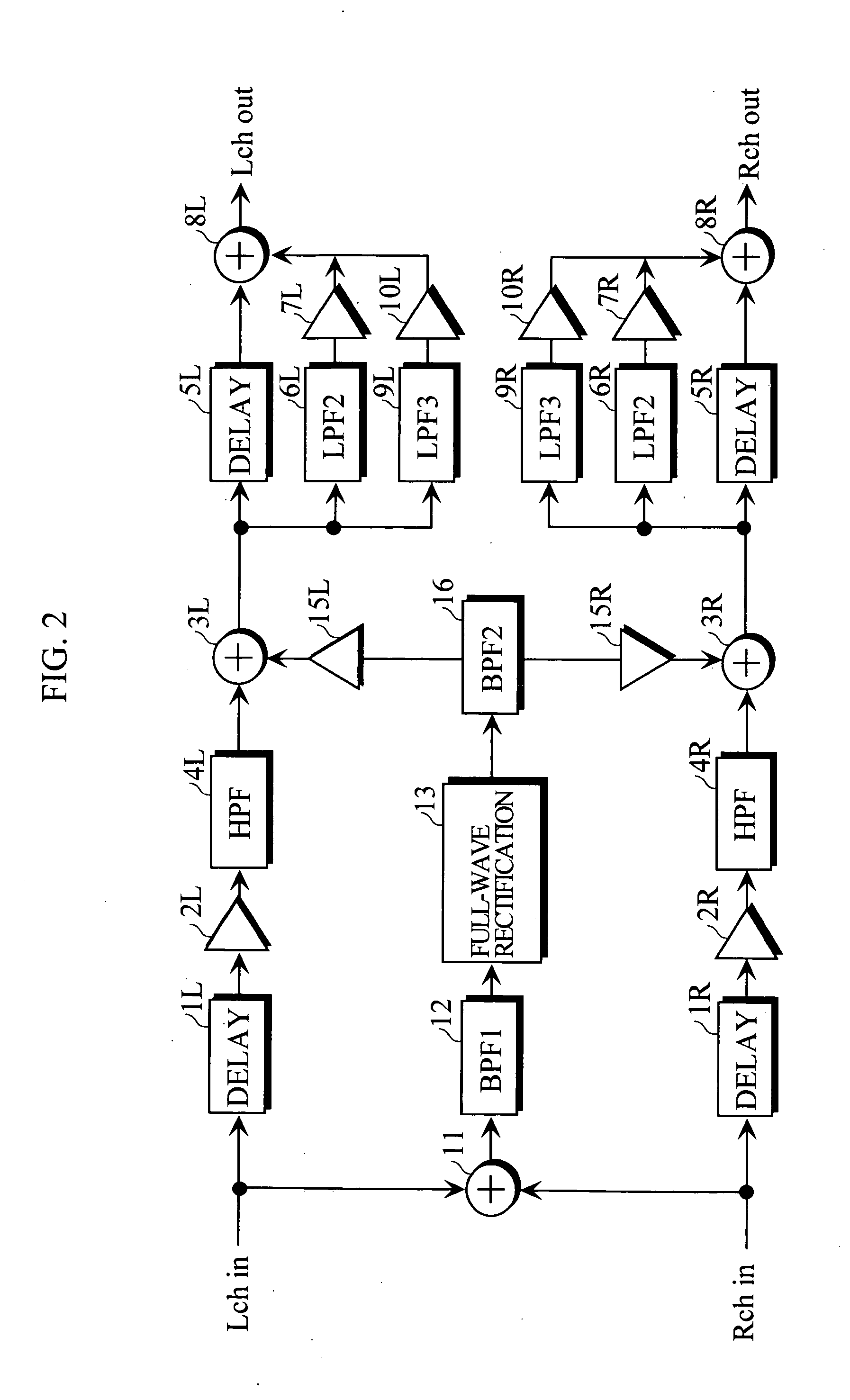
[0048]FIG. 2 shows a constitution of a boost circuit according to a second embodiment 2.

[0049] The embodiment 2 is different from the embodiment 1 in the following points. [0050] (1) High-pass filters (HPF) 4L and 4R are provided not at the subsequent stage of adders 3L and 3R but provided at the previous stage of the adders 3L and 3R. Accordingly, instead of the low-pass filter (LPF) 14 provided at the subsequent stage of the full-wave rectification circuit 13, a band-pass filter (BPF2) 16 having functions of both low-pass filter (LPF1) 14 and high-pass filters (HPF) 4L and 4R is used.

[0051] (2) A series circuit of a low-pass filter (LPF3) 9L (9R) and an amplifier 10L (10R) is provided in parallel to a series circuit of a low-pass filter (LPF2) 6L (6R) and an amplifier 7L (7R). Characteristics of the low-pass filter (LPF2) 6L (6R) and the low-pass filter (LPF3) 9L (9R) are set as shown in a table 2, for example. In addition, when it is assumed that a gain of the amplifier 7L (7R)...


PUM


Abstract

There is provided a first adder which synthesizes input audio signals in a plurality of channels, a first band-pass filter which transmits only a signal in a predetermined frequency band in the audio signals synthesized by the first adder, and a full-wave rectification circuit which generates an even-order harmonic signal of the audio signal transmitted from the first band-pass filter. A lower limit frequency of the first band-pass filter is set at a value such that a frequency interval between adjacent orders of the even-order harmonic signal generated by the full-wave rectification circuit is not less than a critical bandwidth of a signal frequency band from a reproduction lower limit frequency of a speaker to be used to an upper limit frequency of a harmonic wave to be used to boost the bass.

Description

BACKGROUND OF THE INVENTION [0001] 1. Field of the Invention [0002] The present invention relates to a bass boost circuit and a bass boost processing program in which a bass can be boosted when a small speaker or a headphone having a low bass reproducing ability is used. [0003] 2. Description of the Background Art [0004] It is known that when a sound comprising signals 2f, 3f, 4f, . . . which are harmonics of a signal of a reference frequency f is generated, there is a psychological phenomenon in which even when the signal of the reference frequency f is not contained in that sound, the sound of the frequency f seems to be reproduced. [0005] In addition, as a method of generating the harmonic, although there are various kinds of methods, the most simple method is such that even-order harmonics are generated by performing full-wave rectification for the signal of the reference frequency. [0006] The bass reproducing ability is limited by capacity of a speaker mainly. Therefore, a suff...

Claims


Application Information

Patent Timeline
IPC IPC(8): H03G3/00H03G5/00H03G5/22H04R3/04H04R5/033H04S1/00
CPCH03G5/22
Inventor YOSHIDA, MASAHIRO
Owner SANYO ELECTRIC CO LTD
Why Eureka
Try Eureka