Integrated optical devices and methods of making same

a technology of integrated optical devices and optical sub-assemblies, which is applied in the field of optical sub-assemblies, can solve the problems of unsuitable and/or undesirable use in some applications, complicated manufacturing processes, and relatively high cost of typical cans, and achieves the effect of reducing the number of components and rapid and inexpensive production of optical sub-assemblies

Active Publication Date: 2005-08-25
ELECTRONICS & TELECOMM RES INST +1
View PDF6 Cites 67 Cited by
  • Summary
  • Abstract
  • Description
  • Claims
  • Application Information

AI Technical Summary

Benefits of technology

[0017] Among other things then, exemplary embodiments of the invention eliminate the need for a TO can to house the semiconductor laser. Further, use of the lens both to implement desired optical effects and to hermetically seal the semiconductor laser reduces the number of components in the optical path of the semiconductor laser. In addition, wafer scale production of components such as the lens enables relatively rapid and inexpensive production of the optical subassembly.

Problems solved by technology

While TO cans and their associated components provide useful functionality in many cases, the typical TO can possess certain characteristics which can make it unsuitable and / or undesirable for use in some applications.
By way of example, the use of multiple components in the construction of the TO can complicates manufacturing processes and also contributes to the relatively high cost of typical TO cans.
In addition, the use of multiple parts results in a relative increase in the number of potential failure points in the final assembly, especially during shock and vibration.
Further, the configuration of typical TO cans does not make the TO can well suited to high volume production techniques such as wafer scale manufacturing.
While some components of the TO can, such as the laser, can be produced with wafer scale techniques, the other components of the TO can must be produced with more labor intensive and time consuming techniques, and the same is likewise true with respect to assembly of the TO can.
Thus, while the window of the TO can is not employed to implement any particular effect with respect to the optical signal, the inclusion of the window as an additional optical element in the optical path can nonetheless act to compromise the integrity of optical signals transmitted and received in connection with the operation of the TO can and associated components.
Another problem associated with the window of the TO can is that it can place a limitation on the minimum distance the lens or lenses could be placed with respect to the laser and the detector.
As such, this can result in a needed increase in the size of the optical port as well.
Other complications can occur, such as in the case where a lens is incorporated on the TO can in place of the lens, which can result in fairly complicated alignment schemes.
For example, any alignment of the lens on the TO lens cap to the laser or the detector on the TO header may still be compromised when the TO can is hermetically sealed.
Thus, manufacturers that produce TO cans with lenses already aligned will often charge as much as double the lens cost for the TO assembly.

Method used


Image

  • Integrated optical devices and methods of making same
  • Integrated optical devices and methods of making same
  • Integrated optical devices and methods of making same

Examples


Embodiment Construction

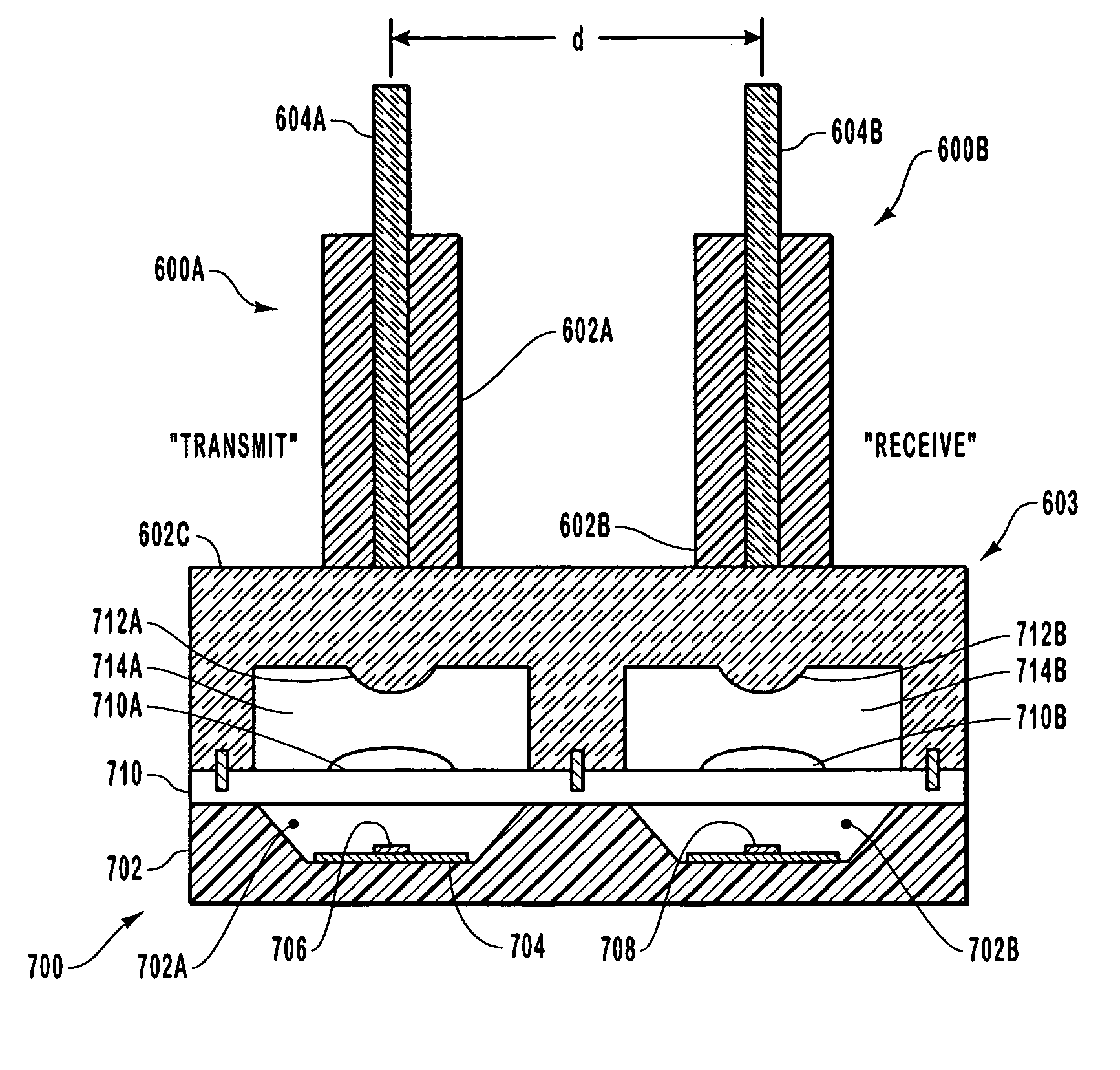
[0035] The present invention extends to optical subassemblies and associated components. More particularly, exemplary embodiments of the present invention concern an optical subassembly that includes a lens which facilitates the hermetic sealing of various components of the subassembly, while also implementing desired optical effects with respect to the optical signals transmitted and received by such optical components.

I. General Characteristics of an Exemplary Optical Subassembly

[0036] As noted earlier, embodiments of the present invention concern an optical subassembly that includes a lens which facilitates the hermetic sealing of various components of the optical subassembly, while also implementing desired optical effects with respect to the optical signals transmitted and / or received by the optical subassembly.

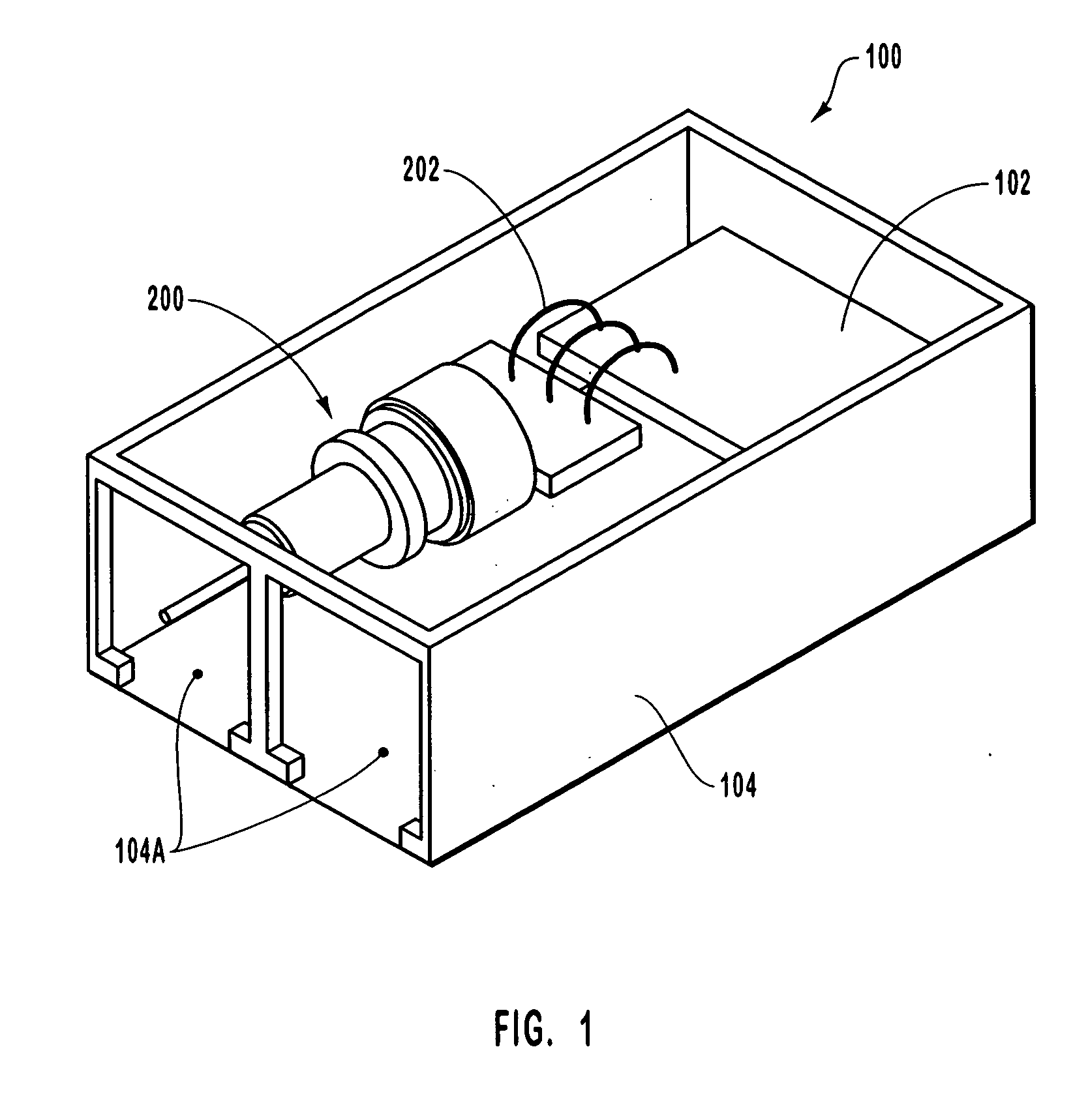
[0037] More particularly, and as outlined in further detail below, exemplary embodiments of the optical subassembly include a substrate that defines a cavity or depr...


PUM


Abstract

An optical subassembly is provided that includes an optical component mounted to a substrate. In addition, the optical subassembly includes a lens package having a lens that is optically coupled with the optical component. The lens package cooperates with the substrate to define a hermetic chamber within which the optical component is disposed. The optical subassembly can be made as an integrated subassembly having both transmit and receive components within the hermetic chamber. Methods in accordance with the present invention include techniques for producing hermetically sealed optical subassemblies in mass-production.

Description

CROSS-REFERENCE TO RELATED APPLICATIONS [0001] The present invention claims the benefit of priority to U.S. Provisional Patent Application No. 60 / 577,035, filed on Jun. 4, 2004, entitled “Integrated Optical Devices”. The present invention is also a continuation-in-part of U.S. patent application Ser. No. 11 / 040,483, filed on Jan. 21, 2005, entitled “Hermetically Sealed Lasers and Methods of Manufacturing”, which claims the benefit of priority to U.S. Provisional Patent Application No. 60 / 538,201, filed on Jan. 22, 2004, entitled “Hermetically-sealed Lasers and Methods of Manufacturing”, and to U.S. Provisional Patent Application No. 60 / 577,035. Each of the foregoing patent applications are incorporated by reference herein in their respective entireties.BACKGROUND OF THE INVENTION [0002] 1. The Field of the Invention [0003] The present invention relates generally to optical subassemblies and associated components. More particularly, embodiments of the present invention concern an opt...

Claims


Application Information

Patent Timeline
Patent Type & Authority Applications(United States)
IPC IPC(8): G02B6/42
CPCG02B6/4214G02B6/4206
Inventor FARR, MINA
Owner ELECTRONICS & TELECOMM RES INST
Why Eureka
Try Eureka