Structure for connecting optical fiber

a technology of connecting structure and optical fiber, applied in the direction of optics, optical light guides, instruments, etc., can solve the problems of reducing the amount of light being transmitted through the optical fiber, affecting the performance of the connecting structure, so as to achieve easy connection, improve the effect of structure, and reduce the loss of connection

Inactive Publication Date: 2005-08-25
TOYOTA JIDOSHA KK
View PDF4 Cites 6 Cited by
  • Summary
  • Abstract
  • Description
  • Claims
  • Application Information

AI Technical Summary

Benefits of technology

[0010] The present invention has been made in view of the above-mentioned problem, and an object of the present invention is to provide an improved structure for connecting an optical fiber to a light-receiving

Problems solved by technology

When the vehicle collides with another vehicle or an obstacle, the optical fiber may be broken or damaged, thereby reducing an amount of light being transmitted through the optical fiber.
This is because a loss in light

Method used


Image

  • Structure for connecting optical fiber
  • Structure for connecting optical fiber
  • Structure for connecting optical fiber

Examples


Embodiment Construction

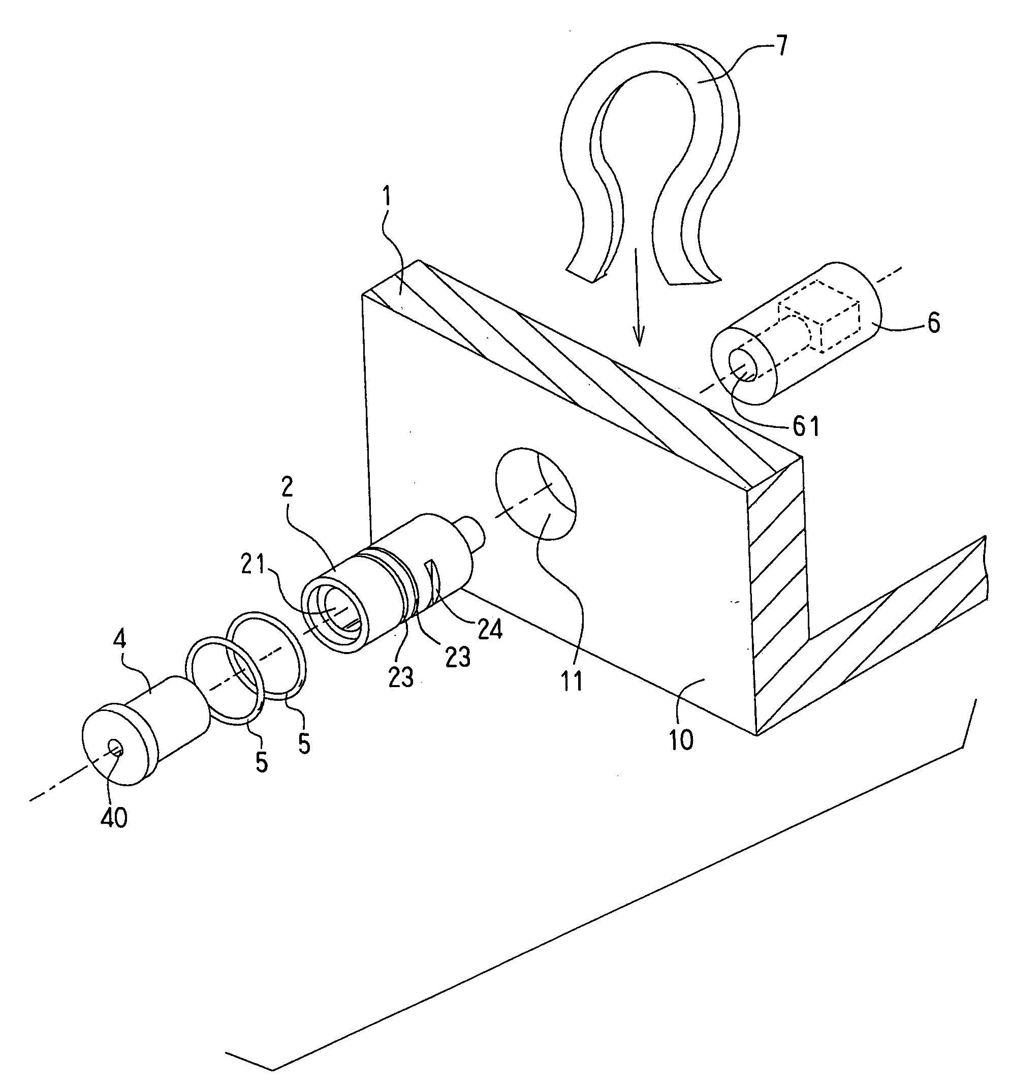
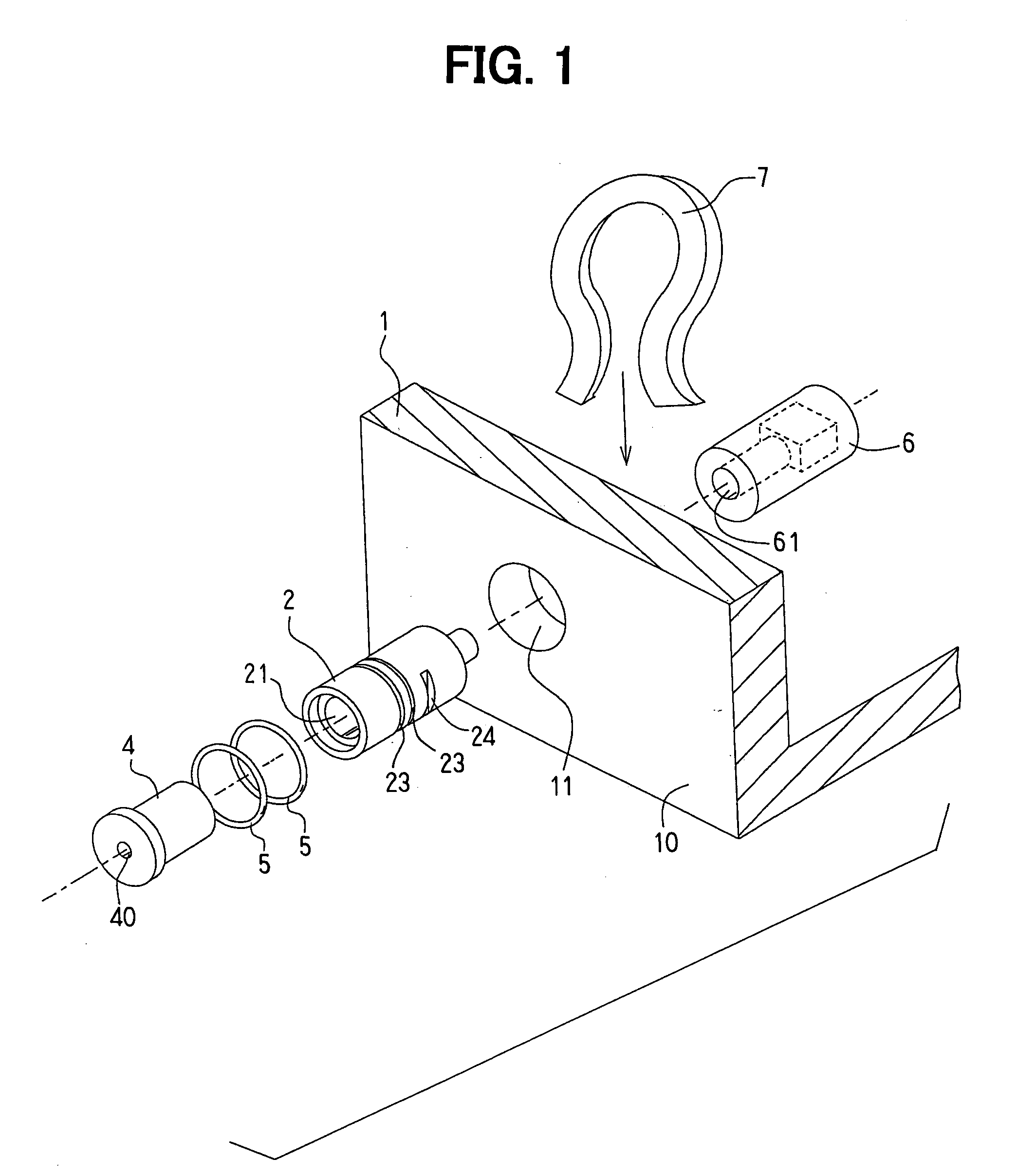
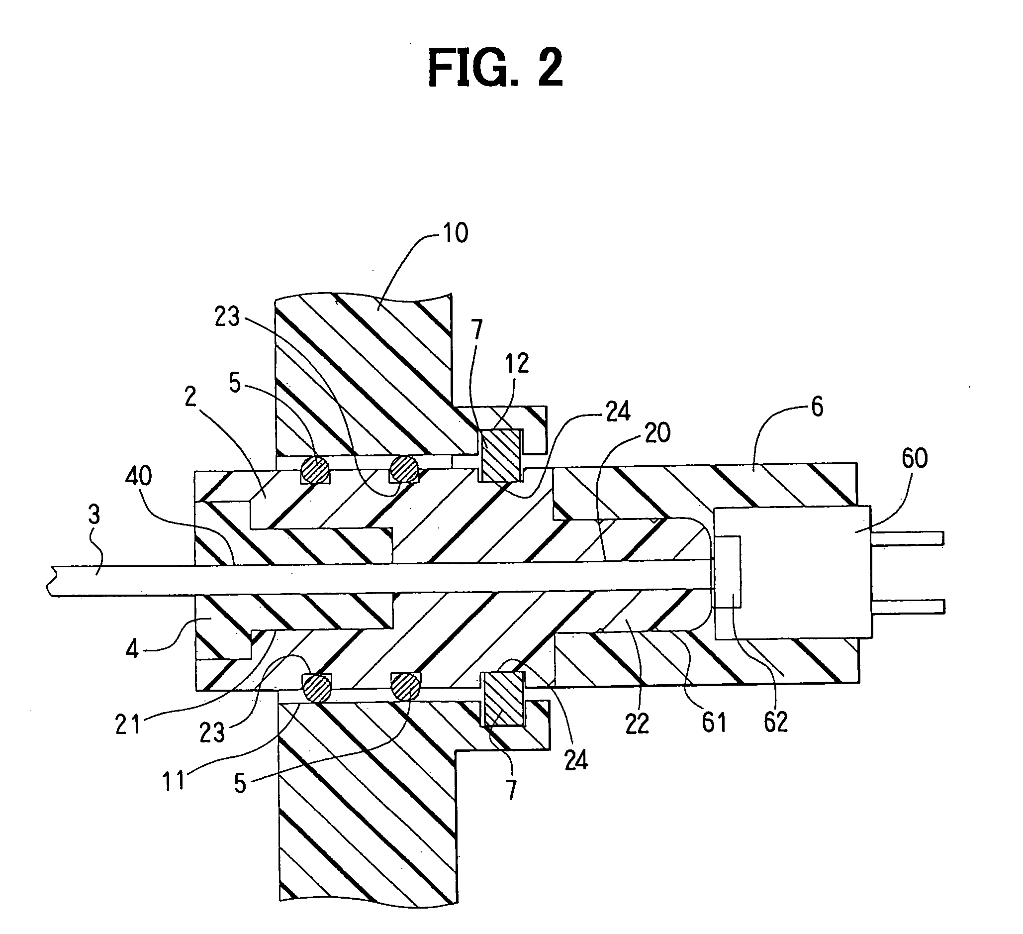
[0018] A preferred embodiment of the present invention will be described with reference to FIGS. 1 and 2. A ferule 2, in which an optical fiber 3 is inserted, is held in a through-hole 11 formed through a wall 10 of an interface box 1. After the ferule 2 is fixed to the wall 10 of the interface box 1, a coupler 6 having an light-receiving / emitting element 60 is coupled to the ferule 2 from the inside of the interface box 1. As shown in FIG. 2, a pair of guide rails 12 is formed on the inside surface of the wall 10, and the ferule 2 is connected to the wall 10 by a stopper member such as a resilient clip 7 held in the guide rails 12.

[0019] The ferule 2 is made of a resin material, and formed in a cylindrical shape having a stepped depression 21 formed at one end (referred to as a front end) and a coupling projection 22 formed at the other end (referred to as a rear end). In the center of the ferule 2, a first center hole 20 through which the optical fiber 3 is inserted is formed. A ...


PUM


Abstract

An optical fiber is optically coupled to a light-receiving/emitting element contained in an interface box. The coupling structure is composed of a cylindrical ferule water-tightly inserted into a through-hole formed in a wall of the interface box, a resilient grommet coupled to the ferule and a coupler having the light-receiving/emitting element. An optical fiber is inserted into coaxially formed center holes of the ferule and the grommet, and an axial end of the optical fiber is exposed at an axial end of the ferule. The coupler is coupled to the ferule so that the light-receiving/emitting element directly faces the exposed end of the optical fiber to establish an optical connection at a minimized connection loss.

Description

CROSS-REFERENCE TO RELATED APPLICATION [0001] This application is based upon and claims benefit of priority of Japanese Patent Application No. 2004-48496 filed on Feb. 24, 2004, the content of which is incorporated herein by reference. BACKGROUND OF THE INVENTION [0002] 1. Field of the Invention [0003] The present invention relates to a structure for connecting an optical fiber to an interface box having a light receiving / emitting element. [0004] 2. Description of Related Art [0005] Recently, an optical fiber is used for various purposes, e.g., as a transmitting line in a communication system or as a load sensor in a collision detecting system in an automobile. JP-A-07-190732 discloses a device for detecting an automobile collision using an optical fiber as a sensor. In this detecting device, an optical fiber is disposed along a front bumper, and one end of the optical fiber is optically connected to a light-emitting element and the other end is connected to a light-receiving unit. ...

Claims


Application Information

Patent Timeline
IPC IPC(8): G02B6/38G02B6/36G02B6/42
CPCG02B6/3897G02B6/4292G02B6/4248G02B6/4202
Inventor INAMOTO, TAKASHI
Owner TOYOTA JIDOSHA KK
Why Eureka
Try Eureka